Last night I had a compact SynSR outrunner nightmare...(compact outrunner motor)

fellow

1 kW
Joined
Apr 1, 2014
Messages
326
Location
Sweden, EU.
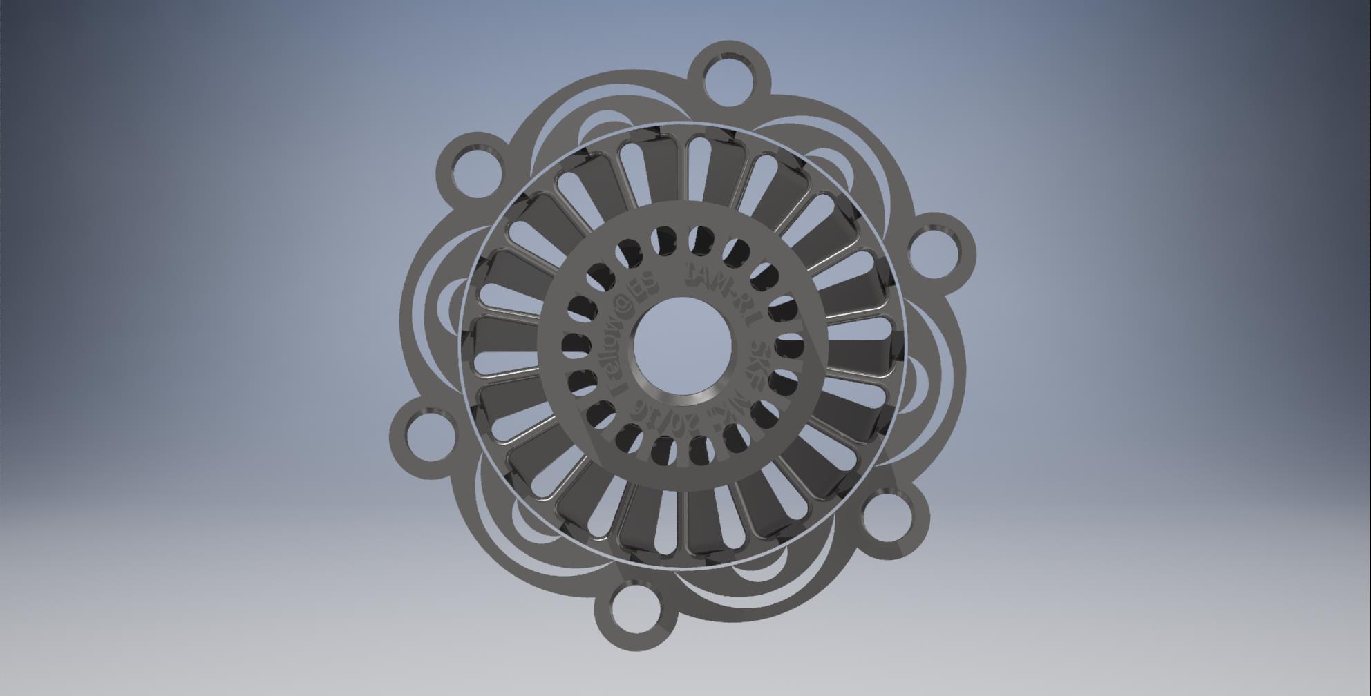
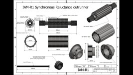
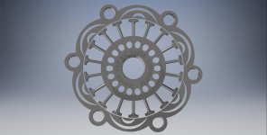
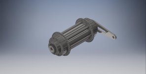
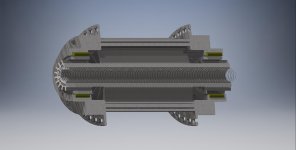
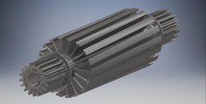
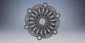
This is what I saw in my dream, compact parametric SynSR outrunner for ebikes:

file.php


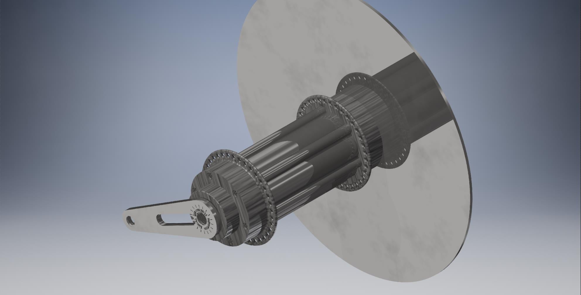
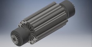
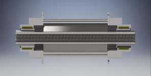
Straight stator version (0 deg skew):
file.php


file.php


file.php


file.php


file.php


203mm brake disc for size comparison:
file.php


file.php


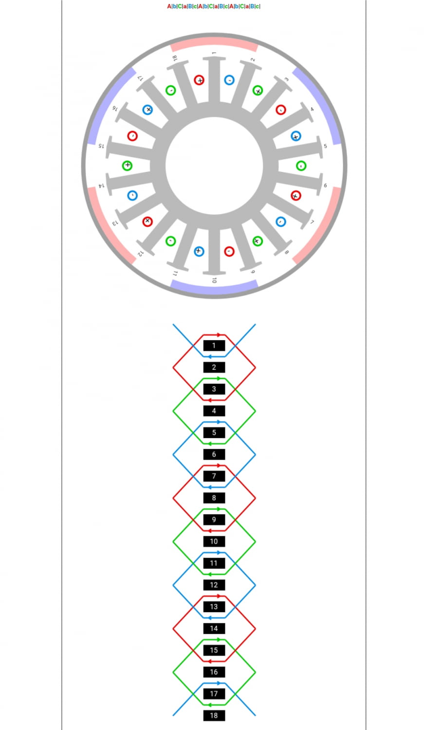
Winding scheme by http://www.bavaria-direct.co.za/scheme/common/ :
file.php


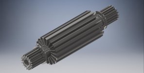
Skewed stator version (10deg):

file.php


file.php


Technical data

Motor type: SynSR outrunner, DD
Gearbox: Not at the moment, but possible due to the modular design
Max rpm: 16k rpm with add-on gearbox.
Bearings: 2 pcs of SKF NKI 16/20. d=20mm, D=32mm, B=16mm, m=48g. Dynamic 15,4kN, static 24.5kN, fatigue@295kg each.
Number of poles: 6
Width: 148mm
Total mass: less than 1999g.
 

Attachments

  • Winding scheme.jpg
    Winding scheme.jpg
    75.8 KB · Views: 1,200
  • IAM-R1 main.jpg
    IAM-R1 main.jpg
    184.4 KB · Views: 1,173
  • V15-0.jpg
    V15-0.jpg
    92.1 KB · Views: 886
  • V15-1.jpg
    V15-1.jpg
    115.2 KB · Views: 886
  • V15-2.jpg
    V15-2.jpg
    80.2 KB · Views: 886
  • V15-3.jpg
    V15-3.jpg
    92.3 KB · Views: 886
  • V15-4.jpg
    V15-4.jpg
    55.8 KB · Views: 886
  • V15-5.jpg
    V15-5.jpg
    61.8 KB · Views: 886
  • V15-6.jpg
    V15-6.jpg
    98.5 KB · Views: 886
  • V15 skewed rotor.jpg
    V15 skewed rotor.jpg
    84.3 KB · Views: 886
  • V15 skewed rotor assembly.jpg
    V15 skewed rotor assembly.jpg
    90.3 KB · Views: 886
nice.

I suppose it is ment as an outrunner?

how do u want to fix the flux forming metal parts in the rotor? On the first picture they seem to float in the air.

Do u have any thoughts about the targeted rpm/torque?

anyway good to see some rare earth less designs!

Regards

Tec
 
Drop the voltage from 150 if you want to have good power density in the controller.

SR is the future! Nice short flux path rotor!

Magnets won't be a part of mature EVs.
 
Yes, kind of a modular outrunner where you can add adapters to customize it for front or rear, 32 holes or 36 holes, DD or bolt on gearbox of choice, freewheel thread and so on. Those adapters are not shown here, but it is the part where the bearings are placed. Material of choice for the adapters is PEEK(PolyEther Ether Ketone) or aluminium.

Stator material is 80% nickel, 5% molybdenum, 13% iron, and small amounts of various other elements such as silicon. There are zillion other suitable soft alloys, unfortunatly all of them very heavy, about 9g/cm3. This is severly limiting its dimensions, few mm more here and there and the mass of the motor skyrockets in a very bad way. Rotor is made of stanched, laminated and industrial epoxy glued sheet metal (0,3mm). Air gap between stator and rotor is drawn as 0,125mm. 0,25mm is the normal practice, in case 0,125mm is too optimistic IRL.

It would be nice to have an ecosystem/world standard where the different manufacturers parts fit with eachother. Like a NEMA standard where adapters to various devices can even be 3D printed by enthusiasts.

Motor is drawn fully scalable, it takes few seconds to change number of poles, slots, and gaps so it meets FEM standards before manufacturing. So it does not have to be 24/18 slot configuration, but this 6-pole configuration fits ebike disc brake standard nicely. To be honest, I drawed it as an initial sketch in few minuts and it is not optimized. It is like a drawing on a restorant napkin:).

Metal parts are fixed by the means of low viscosity industrial grade epoxy glue, in the same manner as ABB and Siemens do it today in their SYNSR inrunners.

As a direct drive 6-pole motor, rpm is 200rpm@10Hz. My wild guess that winding losses kick in about 50Hz-60Hz, so it should be very effective upp to 1k rpm. Grease lubricated bearings are altso the limiting factor, 20k rpm~30k rpm depending of grade, price, quality and model. I would love to help is someone is interested and can make/build this IRL.

Wild guess is that 200W/kg cont air cooled, 400W/kg peak is not unrealistic. ABB says that 88% efficiency is to expect from this size. All of the heat is in the stator. If you look closely, there is a thread inside the stator and holes for liquid cooling add-on adapter.


Infineon has very interesting IPP110N20N3 200V TO220 mosfet, Rds_on 11 mOhm. Two or three of those paralleled...

IPP051N15N5 is their 150V version, Rds_on 5 mOhm. Very suitable for sub 75V systems.

https://www.infineon.com/cms/en/product/power/mosfet/20v-300v-n-channel-power-mosfet/120v-300v-n-channel-power-mosfet/
 
You can see that between those FETs, the 150v part has substantially improved power switching per device than the 200vdc part right?

Or you look at it like units of controller heating per amount of drive power, and you find staying lower voltage improves every performance metric.

The power bussing mass in a vehicle is largely irrelevant, as devices can be packaged to have the busing length approach zero. The BMS cost, complexity and life safety hazards cost orders of magnitude more than a foot of thicker copper/aluminum bus.
 
I agree, 75V system voltage ( using low Rds_on 150V mosfets) is very logical choice for safety and many other reasons.

Not sure about the USA, but in the Low Voltage Directive in the EU states 75VDC as the absolute allowed maximum voltage for "portable" equipment.
Consumer goods with a voltage below 50 V for alternating current or 75 V for direct current are dealt with by the General Product Safety Directive (GPSD) 2001/95/EC, which aims to ensure that only safe consumer products are sold in the EU.
 
Back
Top