Battery Backpack and Retracting Power Lead Project

Qwiksand

100 W
Joined
Nov 10, 2009
Messages
160
Location
Bowie, MD
The goal of this project is to design/build an aesthetically pleasing, elegant solution to carry a pack of LiPo batteries on my back. I've been playing around with using PVC fence posts to hold lipo batteries for a little while (see the Kona build link in my signature) and have found this to be a durable building material, but I've struggled with how to make nice end caps and power/monitoring connection hook-ups. Enter the 3D plastic printer! This build thread will document, hopefully, the process of bringing this concept to reality.

I'll be starting with standard 4" PVC fence posts I get from Home Depot. They measure approx 95mm inside diameter which gives ample clearance to place the 5s 8000mah packs I've been using inside with room for padding and wiring. At this point in time, I'm thinking I'll be using just clean cut, square ends as opposed to the angle cuts I've used on the Kona triangle build.

The tubes:
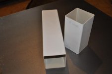
PVC Tubes.JPG

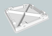
Moving on to the end cap design, it's been a bit of trial and error. I started with the bottom end cap since I plan for this one to be boring and flat with no connectors. Here's the sketchup file:
101'5mm bottom cap.jpg

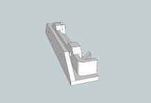
To test fit, I printed the different components to fine tune fitment and save time and plastic. The entire bottom cap takes about 1.5 hours to print. I first designed the inner support structure and printed it to make sure it would fit snugly inside the PVC tube. After this print, I simplified the bracing from 8 to 4 cross pieces- it's plenty strong.

inner support.JPG

Then I needed to check that the outer most aspect of the end cap would sit flush with the outside diameter of the PVC tube.
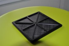
support with endcap.JPG

Once I was satisfied with the dimensions, I printed the full bottom end cap.
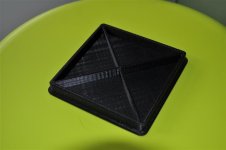
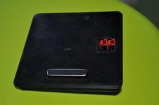
Bottom cap.JPG

Now on to the slightly more complicated top cap. Here's the proposed sketchup design:
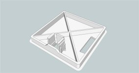
101'5mm top cap.jpg

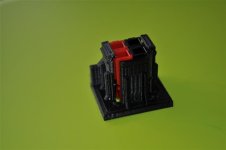
Here's a connector hole test print. I use 4 anderson connectors (2x2 stack of postive and negative) which allow me to connect this pack as 10s2p or 20s1p by changing the external connection from parallel to series. The trapezoidal hole is for a DB25 connector I use to connect the balance leads.
View attachment 1

I spent too much time tinkering with the anderson connector portion of this end cap- I should have just made it so I glue it in place. But that's the fun of playing with the 3d printer; you can make it as complicated as your imagination/skill level allows. This is the first iteration I tried. I was trying to print the tight tolerance 0.5mm grooves to slide the anderson housing into, but this is not possible with my home built rig- the edges are just a little too round to make the tight friction fit necessary.
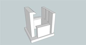
Anderson 4 pack connector.jpg

The little nubs from the prior design were effective, however, so I used that as the main "keeper" portion of the the current design. Here's the sketchup file:
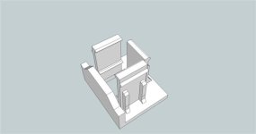
Anderson 4 pack connector2.jpg

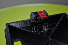
The 4-pack anderson stack clicks nicely in place and then a zip tie will run around the outside (in the groove) to keep it secure as well as allow it to be replaced easily if necessary without printing another top cap.
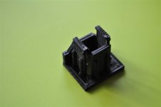
anderson connector test1.JPG

anderson connector test2.JPG

The top cap is a 3+ hour print.
 
Excellent work. I use PVC manrose ducting for my lipo battery build but don't have end caps as yet this is a great development.
 
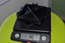
Both end caps weigh in at approx. 82g. At approx $0.05/gram, this is $4.10 in ABS- not too shabby.
endcap weights.JPG

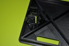
I snapped one of the connector sides off when I test fit the anderson's on this top end cap- good thing ABS is easily fixed (probably stronger than printed alone) with a little acetone. This pick shows the fix, though it's quite blurry.
fixed connector.JPG

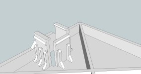
I did a little design modification to the sketchup file and added a little more footprint to the tab supports as well as one additional brace and curved the supports. I also shrunk the nub that catches the side of the anderson connector by .5mm- I haven't printed it to test, but I'll update when I do. It's a fine line between strength and flexibility with this particular design and I'm sure theres a better way- I'm open to suggestions :)
Anderson 4 pack edit.jpg

With the broken side connector reattached and the zip tie holding everything snug.
ziptied connector.JPG

The outer face with both battery connectors in place. The scratches and imperfections seen in the plastic here are from my not-so-pristine kapton tape on the heated bed of the printer.
top cap with connectors.JPG
 
That is awesome! Can you print directly from sketchup files?? What are you using to print these?? Was the machine expencive?
 
Thanks guys!

Whiplash said:
Can you print directly from sketchup files??

Essentially, yes. You just need to download an .stl exporter plug-in and that's what you use to put into the slicing software to generate the g-code for the printer.

Whiplash said:
What are you using to print these??

I'm using a Prusa V2 from the guys at makerfarm.com- I bought this kit: http://www.makerfarm.com/index.php/3d-printer-kits/v2-linear-prusa-kit-deluxe.html You can source your own parts and build it cheaper, but this seemed the easiest way to DIY it for me. You have to get a hold of some parts on your own: smooth and threaded rod, power supply, little odds and ends. There's lots of info on the web, try reprap.org.

Whiplash said:
Was the machine expencive?

I've got around $600 into it. The ABS I use runs around a nickel a gram- I've got a 2.3kg (5lb) roll that I think was about a $100.

It's the coolest thing to watch your designs take shape a layer at a time, right before your eyes!
 
Awesome info thanks! Are the parts pretty strong?
 
The ABS I'm using is stronger than I expected; of course, a lot of it is design dependent. I'm working on some full plastic as well as plastic/metal hybrid mounts for a couple of my bikes right now. With the right amount of engineering/design forethought, I think a moderately powered mid-drive mount is possible (thinking about a Turnigy 6374 sized motor)- it's a project for another day though :lol:
 
Nice work, when nechaus started posting about 3d printers a few months ago about I was talking to him about making pretty much the exact thing you've just done for my lipo boxes. How do you find the fit ? My concern was that there'd be too much flex in the PVC that they'd just fall out with bumps. I guess a bit of glue would solve that problem and you could worry about it later if you ever needed to remove it. I've used PVC for years and used screwed in MDF or perspex endcaps but something specifically printed makes a neater solution.
 
With the printed parts you could easily include bosses / chunky mounts for screws through the PVC. so I would think you could easily secure the ends.

It looks fantastic. Well done.

Andy
 
This fit is tight, but not tight enough to hold 10-12 lbs of lipo in the tube. These end caps will get a a couple rivets to hold 'em on and on the next printing i'll probably design in some recessed nut mounts into the perimeter. I thought about doing that on this batch, but went with rivets for simplicity.
 
I'll be mounting this battery tube to an old, re-purposed camel back that I've hacked everything off but the straps and back mounting fabric. So on to fabricating a mounting solution.

Originally, I thought I wanted to use a basket-like structure to secure the bottom of the battery tube to the backpack. This would provide for a very strong connection point and would make for a secure fit as well. Here's about 1/2 a pound of failed or abandoned prints/designs working toward this goal:
failed bottoms.jpg

The first design I tried printing used a solid, 15mm thick bottom with 12mm thick walls. This was way overkill and turned out to be nearly impossible to stick this large of a mass of ABS to my print bed without severe deformation. So, I learned from this and started shrinking walls and adding voids to reduce the ABS shrinkage/warping problem, but still trying to maintain strength. I also found that by adding little recessed spaces in walls, I could dramatically increase stiffness/strength of a wall while reducing the amount of plastic needed to print it: a win-win situation!

So I came to this design.
Backpack Bottom.jpg

But when printed, it turned out to look a little like a big easter basket and is still totally overkill for my needs.
basket bottom.jpg

Which led me to another redesign. I plan to hold the battery tube in position with a couple of plastic buckle straps, so I realized I really only needed to keep the tube from sliding off the bottom or sides.
Backpack Bottom v2.jpg

I'm happy with how this print turned out. It held my weight (190lbs) when I stood on it to test it out (I didn't stomp or jump on it- its a five hour print after all :oops: - but it held and felt solid).
ABS bottom.jpg

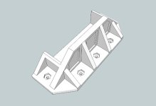
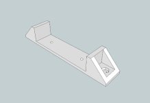
I'll also be using four of this little mounts (one on either side of the buckle straps) along the body of the battery tube.
battery mid mount.jpg

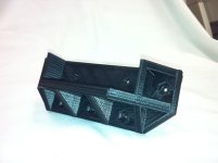
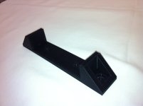
They printed nicely as well.
ABS mid.jpg

All of the printed tube mounts will rivet to a 4" x 1/8" strip of aluminum via the little holes you see in the middle of each mount and then I will bolt the plastic mounts to the backpack using the recessed nut holes. I'm hoping this will work as I don't currently have a plan "B" :)

I should have some almost completed battery backpack pics up this weekend, stay tuned!
 
I think there was no need to do the anderson chassis mount since those are available for really good prices. Probably less than it cost to print it in a 3D printer.

http://www.powerwerx.com/powerpole-accessories/powerpoles-chassis-mount-2-sets.html

And I've seen them for ~4$ somewhere else and with the opposite connector. Kudos on the rest thou really nice build.
 
migueralliart said:
I think there was no need to do the anderson chassis mount since those are available for really good prices. Probably less than it cost to print it in a 3D printer.

http://www.powerwerx.com/powerpole-accessories/powerpoles-chassis-mount-2-sets.html

And I've seen them for ~4$ somewhere else and with the opposite connector. Kudos on the rest thou really nice build.

Thanks for the link, I hadn't seen those before. Realistically though, there's prolly a maximum of $0.15 in plastic in my anderson mount. But I can't get near the same strength as the injection-molded stuff in such a small piece- Im gonna check these out.
 
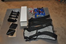
Alright, back at it. I laid everything out here, you can see all the main parts. The printed plastic parts will rivet to the 4" aluminum strip and also bolt (using grommet style washers) to the camel back shell. The cinch straps rivet to the aluminum channel as well.
all backpack parts.JPG

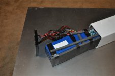
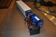
Shoving the batteries in the tube- I'll be revisiting this step again as there is a lot of extra wire length here that just makes a mess and chance of future failure.
Batts in tube2.JPG

I cut the shrink wrap on this battery to check out the foil pouches, there was no significant trauma 8)
Batts in tube1.JPG

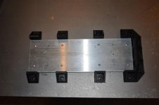
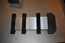
Here you can see the plastic parts mounted to the aluminum.
mounts on aluminum front.JPG

And the back side.
mounts on aluminum back.JPG

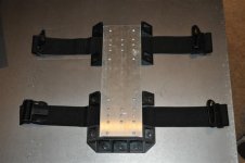
With the straps installed- this was a pain in the a$$ with all these rivets. I drilled the holes then used a torch to heat an awl to melt holes in the nylon webbing. The back side uses a washer with the rivet to help distribute load.
straps on aluminum.JPG

Checking fit of the straps and mounts- everything is snug.
View attachment 7

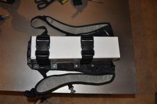
With the full mount set-up attached (bolted) to the camel back.
mount on backpack.JPG

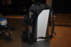
And with the battery cinched in, ready to roll.
battery in back pack.JPG

I may end up either adding another cinch strap higher up on the tube or just move the existing mount higher. With the backpack on, the top of the battery tube extends backward, away from the top of my back approx 3-4". This makes the fit on my mid/low back perfect, but I'm not sure that this is the best mounting solution. I'll have to put some miles on it first.

Next step is making some pretty power and monitoring (cell-logs) lead hook-ups.
 
Less than 24 hours and I'm changing direction again :lol: After thinking about the ungainliness of having 4 lipo bricks (2 x 2 configuration) in one tube, I'm going to be converting over to 2 brick tubes- 37v nominal 10s,1p 8000mah. I'll be able to use this version of the backpack to carry single tubes for short trips and I'm working out making a double tube holder backpack that will carry 2 tubes (maybe more :twisted: ) in a side-by-side configuration. The four pack tube is just long enough to be inconvenient; it won't fit in any normal MTB triangle and it looks a bit out of place being carried on the back. More to come when I have pics of my progress.
 
Oh, I totally missed the part of this project (ie the title! :roll: ) where these was going to end up as a backpack!
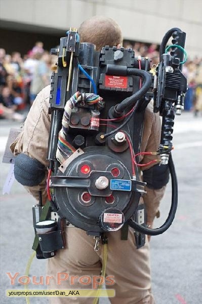
Any reason why you want the battery tube so "thick" ? Given the load is across your whole back anyway why not have a slimmer/low profile case ? You could print this in parts on your printer too. The whole thing would be about the size of a large text book.

That said if I had a 3D printer I'd aim to have my high powered battery backpack look like this :lol:

Proton-Pack.jpg
 
Hyena said:
Oh, I totally missed the part of this project (ie the title! :roll: ) where these was going to end up as a backpack!
Any reason why you want the battery tube so "thick" ? Given the load is across your whole back anyway why not have a slimmer/low profile case ? You could print this in parts on your printer too. The whole thing would be about the size of a large text book.

That said if I had a 3D printer I'd aim to have my high powered battery backpack look like this :lol:

Proton-Pack.jpg

Nice pic, totally mad max!

I might try printing my own tubes someday, but I'm sure I'd end up wasting $100 worth of abs doing it :lol: I'm sticking with the PVC tubes for 1) cheapness 2) crash-worthiness (I hope anyway, they're certainly stronger than the same thickness printed ABS plastic). I could slice these things down the middle and shave a bit outta each side to make them a little sleeker, maybe a project for another day. You guys (Aussies) and Europeans seem to get a rectangular vinyl tube I can't find over here.
 
Qwiksand said:
Nice pic, totally mad max!
Totally ghostbusters!
Fair enough on the expense factor though, the premade PVC pipe is hard to beat for cost. I'd argue that in a backpack scenario it's less critical and easier to offer impact protection as you need never see the battery. Hell I'd probably built it into the base of an existing backpack (wrapped up in high density foam) and just run the wiring to an external faceplate with the main discharge and balance connector on it.
 
Hyena said:
Totally ghostbusters!
D@mn, totally missed that it was a proton pack :oops:

Hyena said:
Hell I'd probably built it into the base of an existing backpack (wrapped up in high density foam) and just run the wiring to an external faceplate with the main discharge and balance connector on it.

But then what would I do with my 3d printer!?! :lol: I agree, that would be the easiest route. But I have visions/aspirations of these tubes being easily hot-swappable and mountable to my different bike frames as well as backpacks.
 
Hot swappable is the future for ebikes, your design is looking good man!

Another problem is the cord going down to the frame, any ideas on how to make this more user friendly and not get tangled up with the rider? Hmmm, I wonder how hard it would be to use a quick disconnect device that is held together with strong magnets and has a flip top lid that flips down to cover any exposed connector on the battery side when disconnected.
 
etard said:
Hot swappable is the future for ebikes, your design is looking good man!

Another problem is the cord going down to the frame, any ideas on how to make this more user friendly and not get tangled up with the rider? Hmmm, I wonder how hard it would be to use a quick disconnect device that is held together with strong magnets and has a flip top lid that flips down to cover any exposed connector on the battery side when disconnected.

I've got some ideas on this as well. The one I'm currently leaning toward will incorporate a spring-loaded reel for the main power cord to the bike- the cord will be able to extend/retract with the rider movements and not have a bunch of extra slack that gets tangled. Anderson connectors work pretty good as is for quick release, but incorporating magnets is something I'll look into- blatantly stealing your idea!
 
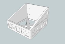
Just got done drawing these, so no prints yet. This is the new model for the bottom cap with integrated nut traps, no more package tape :p

101'5mm bottom cap nut traps.jpg

And this little contraption should allow me to drill the holes in the PVC tube in the right spots.

nuttrap drill template.jpg
 
Back
Top