Two speed 'gearbox' (now up to four speeds!)

Joined
Apr 17, 2008
Messages
607
Location
Ankara, Turkey
Wasn't sure where to put this, so figured this section was a safe bet.

I was sitting this morning - having a cup of coffee - and trying to think of a way to set up a two-speed gearing mechanism. This is what I came up with - not sure if it's viable - comments would be very welcome!

Twospeedgear01.jpg


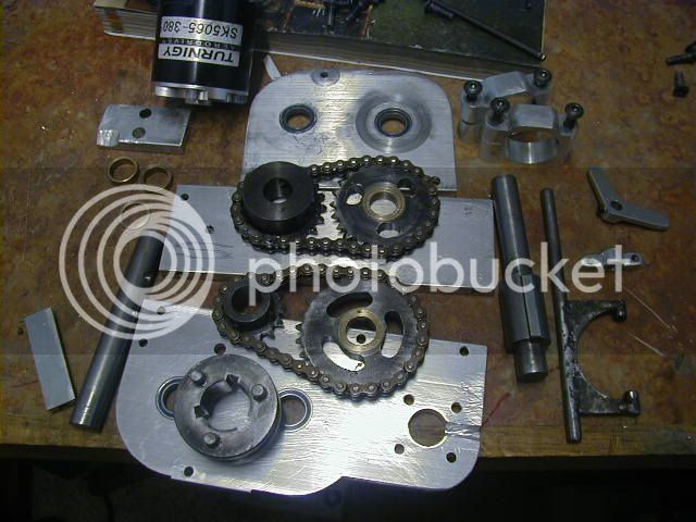
So, basically we've got two motors spinning a common jack-shaft - though this would work for any number of motors. On the jack-shaft, you have a free floating 'swing-arm' (in blue below) that's mounted via bearings to this shaft. You also have a smaller pulley that spins the green bits (pulley and cog). For the red unit, we've got teeth on an inner cog, and on the outer periphery (both connected to each other and another shaft that ultimately drives the front drive sprocket.

So, in low gear (blue lever forward), the green cog engages the outer ring, high gear (lever backwards) it engages the inner cog. Of course the motors will have to run in reverse directions between low and high gearing. To optimize this, one would want to construct a 'hijacking' circuit along with some reed switches and hall sensors to determine the levers position and direction of movement as well as the RPM of the dual-gear cog. I'm no electronics engineer, but in theory at least, this should be do-able.

As you move the lever, the highjack circuit would take over the throttle input, and keep the green cog's speed matched with the gear it's disengaging. Once the teeth clear each other, regen would be activated to slow down the green gear - in preparation for going into reverse. The regen would only be engaged if the cog is moving away from a gear. As the cog/lever hits the mid point, the regen will be turned off (basically 'neutral' gear where you are freewheeling). Once it moves away from midpoint, the controller/s would be switched to reverse and the highjack circuit would spin up the motors so the green cog speed matches the speed of the gear it's about to engage. Once the teeth mesh, control of the main throttle would be returned to the driver.

Stupid Idea?


Twospeedgear02.jpg
 
Not bad... I like the inside/outside form.

Instead of crashing spur-gears together, you might consider having two cogs engaged, one on inner, one on outer... then have separate belts to each with overrunning clutches like in Miles' 2-speed RD trannys.
 
Clever design, and it looks like if you were to stop and shift it, that it would work fine. I can't see that working for shifting on the fly though... unless you had some crazy motor speed synchronizer system to match motor speed to the output shaft speed.

You may be interested in a similar design though, that takes up a similar space, and can offer a similar large range of reduction. It's a planetary reduction where the brace for the planets has a bit of motion to slide in and out, yet the ring gear is extra wide enough that the planets always stay fully meshed. The hub has dogs on the face that meshes into the ring gear holder face when it's pushed in, or freely rotate and create the gear reduction when it's popped out. This way, you get the alternate between locked solid, or a 3-4:1 reduction, and the gears always all stay meshed, only the dogs need to engage or disengage, and that happens to be what dogs do VERY well. :)
 
TylerDurden said:
Not bad... I like the inside/outside form.

Instead of crashing spur-gears together, you might consider having two cogs engaged, one on inner, one on outer... then have separate belts to each with overrunning clutches like in Miles' 2-speed RD trannys.

I think I understand - Though I'm having difficulty visualizing the 'overrunning clutches"....... I'll admit I've zero experience with clutches - I'll have to do some research on that....


liveforphysics said:
Clever design, and it looks like if you were to stop and shift it, that it would work fine. I can't see that working for shifting on the fly though... unless you had some crazy motor speed synchronizer system to match motor speed to the output shaft speed. )

That's the idea behind the theoretical "hijacker" circuit. Hall sensors on the green pulley, and another one on the red section, and you should be able to determine relative speeds and send the necessary input to the controller to match everything. Of course the actual electronics and programming are way beyond me..... :)

liveforphysics said:
You may be interested in a similar design though, that takes up a similar space, and can offer a similar large range of reduction. It's a planetary reduction where the brace for the planets has a bit of motion to slide in and out, yet the ring gear is extra wide enough that the planets always stay fully meshed. The hub has dogs on the face that meshes into the ring gear holder face when it's pushed in, or freely rotate and create the gear reduction when it's popped out. This way, you get the alternate between locked solid, or a 3-4:1 reduction, and the gears always all stay meshed, only the dogs need to engage or disengage, and that happens to be what dogs do VERY well. :)

I was able to follow you up to the point where you mentioned the dogs, and then I got lost....... :( Do you have anything that illustrates this?

I'm starting to think I'm way out of my depth here....... :wink:

.
 
michaelplogue said:
TylerDurden said:
Not bad... I like the inside/outside form.

Instead of crashing spur-gears together, you might consider having two cogs engaged, one on inner, one on outer... then have separate belts to each with overrunning clutches like in Miles' 2-speed RD trannys.

I think I understand - Though I'm having difficulty visualizing the 'overrunning clutches"....... I'll admit I've zero experience with clutches - I'll have to do some research on that....

OK.... I think I've got you now. Got something in my head that might work - plus eliminating the need to reverse the motors.
 
OK... Here's what I came up with, though I don't think it will work well - I'm thinking this would be better using gears and chains.

Twospeedgear02-a.jpg


Twospeedgear02-b.jpg


Twospeedgear02-c.jpg


Each of the two smaller pulleys on the first jack-shaft are on bearings and have either friction plates or the dogie gears (still not sure exactly how those work - need to do more research.... :oops: The white 'clutch' piece is on a splined section of the shaft so it can slide left to right while spinning with the jack-shaft. The 'C' shaped piece runs in it's center groove and slides left to right - pushing the white part against either pulleys' friction plate or dog gear.

I worry most about the friction from the dealie-bob (more commonly known as the' do-hickey') that moves the clutch back and forth......
 
^^^Right. Very similar to Thud's 2-speed tranny... his clutch-piece mostly differs by having lugs (dogs) that engage slots in the input gears.
 
I'm having difficulty visualizing the "overrunning clutches"

Here's a couple threads from a while back that had some good pics to illustrate over-running clutches and dog-clutches in a 2-speed trans. RC cars use a tiny plactic-geared 2-speed similar to what I think you're showing. Its a proven idea that only needs to be scaled up to E-moto size...

"Idea, cheap robust 2-sp transmission"
http://endless-sphere.com/forums/viewtopic.php?t=9695

"2-speed tranny idea"
http://endless-sphere.com/forums/viewtopic.php?f=28&t=10782&start=0
 
TylerDurden said:
^^^Right. Very similar to Thud's 2-speed tranny... his clutch-piece mostly differs by having lugs (dogs) that engage slots in the input gears.

And here I thought I was being clever.. :p For my next trick, I'll be inventing something that will revolutionize the world - I'm going to call it the "wheel!" :wink:

That's exactly what I'm looking for! I had no idea the dog clutch was so simple..... You learn something new every day!

I noticed that the slots on the gears were of different length. Is there a reason for this? I'm guessing that longer slots are better.....

td-5.jpg
 
Ok... I know this is silly - you just don't normally need four speeds for an electric motor, but what the heck! I was actually trying to figure out how to take Thuds innovative two speed design (beautiful work Thud!), and modify it for three gears - one for super torque billy goat climbing power, one for normal cruising, and an overdrive for highway speeds. I was playing with all kinds of crazy levers and whatnot and eventually fell asleep in front of the computer - thinking of ways where I can choreograph the movements of the dog gears. When I woke up, I thought "Music Box!"

diy_music_box-754106.jpg


Originally the grooved tube was going to just be a plate that would move back and forth. But that was taking up a lot of space. Then it struck me to turn it into a tube and it will do the same thing - just rotate it to move the arms back and forth.


Neutral:
FourSpeedMusicBoxTranny01_a_001_col.jpg


First Gear:
FourSpeedMusicBoxTranny01_a_002_col.jpg


Second Gear
FourSpeedMusicBoxTranny01_a_003_col.jpg


Third Gear:
FourSpeedMusicBoxTranny01_a_004_col.jpg


Fourth Gear:
FourSpeedMusicBoxTranny01_a_005_col.jpg


The music box tube rotates on the fixed (gray) shaft with a pair of bearings as seen below. this would probably be better if I used the same size pulley/gears on the first jack shaft and varied the sizes on the drive shaft - allows the motivator arms to be shorter and less lateral stress when shifting gears.

FourSpeedMusicBoxTranny01seethrough.jpg
 
That's called a sequential... lol

The standard in motorcycles and various other racing trannys since, maybe the 1950's? Earlier?

It's fantastic that you were able to also visualize and create the idea yourself though, and you did a great job CAD'ing it all out.
 
Damit! Is there nothing left for me to invent?!! LOL! :lol:

Guess I better start doing some reading - figure out what has already been figured out....... :wink: I guess that's one of the drawbacks from being a nerd instead of a piston head in school - you don't learn about these sorts of 'mechanicalized' things playing Dungeons and Dragons.....

At least I know that I'm not a total idiot. If I'm re-inventing the wheel, that at least means I'm as smart as the guy who invented it in the first place.....


caveman_harley.jpg


Back to the drawing board..... 8)

.
 
This sort of thing happens to me quite often. Now whenever I get a good idea, you know, one that feels, like, "wow, this is a REALLY good idea!" I am instantly suspicious.

Look on the bright side, now you understand motorcycle transmissions from first principles. A priori knowledge always feels so SOLID, you know?

Katou
 
About monthly in college I would get some idea that I thought was revolutionary for an improved valve-train design for ICE's. I would make lots of sketches and get pretty excited. I would always pin down the mechanical engineering dept head (and old guy who was extremely laid back and sharp), and he would tell me, ehh, it's been tried that way, and they improved it with this, and tried that, and they all sucked worse than tappet valves for x-reasons. I had started thinking this guy might be full of sh*t when he would tell me every design i came up with had all ready been tried, along with lots of variations of it. He referred me to this book, which I still have, called, "high speed reciprocating engine valve design." It's got a copyright in the 60s. Sure enough, this book has about 250pages, with another design that's been tried for every 2 pages or so... along with the pros and cons of each design, history of implementation, etc.

If you're serious about tranny design, I would highly recommend getting some resources on tranny design history and development. I would imagine there have been 100x as many tranny designs as ICE valve designs over the years, and the most designs you see, the more ideas you get to incorporate into your own thoughts/designs.
 
So after all has been said and done, why not apply a 4 speed transmission to e-bikes?

Friction right? I think I saw a guy on the internerd get his CB750 chassis up to 90 miles an hour (~140 km/h) with an electric motor strapped to the gearbox. Didn't run for very long though.
 
Kim you need to download solidworks 2010! Easy, powerful, with great tutorials. the profile module is top notch, and all bolts, nuts, screws, profiles ext are in toolbox, a great included library.
 
bzhwindtalker said:
Kim you need to download solidworks 2010! Easy, powerful, with great tutorials. the profile module is top notch, and all bolts, nuts, screws, profiles ext are in toolbox, a great included library.

I actually do have a copy of Solid Works already buddy... I haven't got it installed atm though
I have tried all different CAD programs but i don't have the patience i can sketch out what i want in 1/10th of the time
just doesn't look as slick Less time i spend iun front of a PC and in my workshop actually fabricating the better.... haha...

KiM
 
Back
Top