
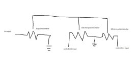
This is my first post here, so thanks in advance for all your help. I'm running the setup as shown in the attached picture with two motor controllers. the two 100 ohm potentiometers are 'stacked' so they move together. The stacked potentiometer works great to divide the controller input voltage, but it has made my throttle really touchy. I will get zero or hardly any throttle for 90% of the twist then at the last little bit of throttle it gives full power. So right now it's basically on/off. Does anybody have any experience with this setup/can explain what is going on here and how I can fix it? Thanks!
You are using an out of date browser. It may not display this or other websites correctly.
You should upgrade or use an alternative browser.
You should upgrade or use an alternative browser.
Steering multiple controllers. Help!
- Thread starter nkeeley
- Start date
Kingfish
100 MW
I am confused: Why are you trying to make a master throttle when ONE will drive both controllers? ")
~KF
~KF
Lebowski
10 MW
I have no clue what you're trying to achieve but I think you should swap the values, use two 5k where there are the 100's and use 100 where you have 5k.
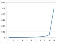
Ok, so I was working through the calcs and only got as far as defining the total circuit current, but it's already indicative of my problem. I've attached a quick graph that shows circuit amps ( y axis) against throttle twist (x axis). I'm getting what appears to be an exponential when I want a linear response.
Long story short, I'm trying to make a cheap 'drive by wire' setup. The 5k throttle is just a magura 'twist' type throttle and the 100 ohm stacked potentiometers are connected to the base end of a steering wheel. I tried reversing the values of the potentiometers as you suggested, but I still get this exponential response. Anyone know of a solution to this without getting a plc involved?
Thanks!
Attachments
Kingfish
100 MW
Lemme guess:
By your DbW, you are using one master throttle, and the wheels are part of steering, so as you turn the wheel, throttle is attenuate d on the slower wheel, such as would be required by a 3W or 4W vehicle having two driven wheels.
Are we close, cos otherwise I yam confus'ed. :?
Remotely, KF
By your DbW, you are using one master throttle, and the wheels are part of steering, so as you turn the wheel, throttle is attenuate d on the slower wheel, such as would be required by a 3W or 4W vehicle having two driven wheels.
Are we close, cos otherwise I yam confus'ed. :?
Remotely, KF
Kingfish
100 MW
Well, I did it with a single throttle - but for Front & Rear. And to eliminate/reduce contention I made the wheels physically different with 26" in front and 24" in the rear. On Cruise, one wheel will drive and the other will freewheel - it doesn't matter which one; they alternate at random.nkeeley said:Kingfish,
Now if I am understanding you correctly, yes, that is exactly what I am trying to do. Is there a simple solution?
However I think you have two in parallel, both front or both rear - and instead of a mechanical differential you need an electrical one. This brings the discussion to AWD vehicles.
Mathematically, regardless of the master throttle position, you want 100% signal on the outboard wheel, and attenuate the inside wheel based upon a couple of vectors: Turning radius, and accelerometer. I might want to add a digital comparator and use a microprocessor to calculate the attenuation. The other consideration is traction, and being able to apply power when one wheel is in soft ground and the other on firm; like posi-track. Or we could look at limited slip systems designed specifically for 4-wheel drive.
Regardless, I would not attempt a mechanical solution to advance/retard individual motor POTs based on steering because of the importance of vehicle speed and terrain. This is in fact a complicated critter to solve in a topology where both wheels are forward or back. Comparatively speaking, I had it easy... and mine was a challenge! :wink:
Let's look at the problem from another angle: What type of motors are we using? Are they Direct Drive? Is this a car, quad, or lightweight recumbent?
Curiously, KF
Mine is a rear wheel drive lightweight farm vehicle. I just used a double (stacked) linear potentiometer on the steering wheel to to act as a double voltage divider and sent the split voltage to each motor controller (one drives the rear left wheel and the other drives the rear right wheel). If I was going at high speeds on roads, I would agree that I need more complex controls. But I'm running slow (3 mph max) on soft ground. The steering actually works just like I want. The problem is the master throttle gives me the exponential response I posted. So I have no throttle control for 90% of the twist and then all of a sudden I'm at full throttle. Does that make it clearer or more confusing?
Kingfish
100 MW
Wait! I know this problem cos I too had an AWD tractor with a master throttle, a foot-actuated forward/reverse, & left/right brake that could be locked together.
Even though you are going slow, we still need to attenuate the inside wheel(s) otherwise you're sort of crab-turning. Now I can visualize your approach to the problem well. Master Throttle is like a lever, instead of like a foot pedal. On the tractor, the differential had limited slip, or I could lock it in for posi-trac.
When you turn the steering wheel, does it rotate more than one full turn - as with mechanical advantage, or is it like power steering?
The Throttle signal - at least the type I am used to working with for BLDC ebike hubs runs between 1.8V to 4.5 VDC; the microprocessor on the Chinese controllers operate best in this narrow range. I don't know anything about your controller(s) - but if you know the make/model - that will help. I am thinking that we just need to apply very slight resistance when fully turned.
Looking at the schematic of one of my projects...
Knowing your type of throttle and controllers will greatly help. The EE graybeards on this forum can chime in on the ohms. Do you have a multimeter or scope where you can track the rise/fall of throttle voltage as you turn the wheel? I think you will need also a trim pot on each channel for balance.
Lastly, before diving into left/right attenuation, the motors should work in unison and balanced with the Master Throttle alone - and without leaps in power levels or dead zones. This part has to work flawlessly before adding complexity, make sense?
Neat problem 8)
Farmer KF
Even though you are going slow, we still need to attenuate the inside wheel(s) otherwise you're sort of crab-turning. Now I can visualize your approach to the problem well. Master Throttle is like a lever, instead of like a foot pedal. On the tractor, the differential had limited slip, or I could lock it in for posi-trac.
When you turn the steering wheel, does it rotate more than one full turn - as with mechanical advantage, or is it like power steering?
The Throttle signal - at least the type I am used to working with for BLDC ebike hubs runs between 1.8V to 4.5 VDC; the microprocessor on the Chinese controllers operate best in this narrow range. I don't know anything about your controller(s) - but if you know the make/model - that will help. I am thinking that we just need to apply very slight resistance when fully turned.
Looking at the schematic of one of my projects...
- Resistor Throttles range between 0.25 to 4.5 VDC
- Hall effect Throttles range between 0.8 to 3.65 VDC
Knowing your type of throttle and controllers will greatly help. The EE graybeards on this forum can chime in on the ohms. Do you have a multimeter or scope where you can track the rise/fall of throttle voltage as you turn the wheel? I think you will need also a trim pot on each channel for balance.
Lastly, before diving into left/right attenuation, the motors should work in unison and balanced with the Master Throttle alone - and without leaps in power levels or dead zones. This part has to work flawlessly before adding complexity, make sense?
Neat problem 8)
Farmer KF
Yes, what you're saying makes sense. And like you suggested, I'm just trying to work out the basic system operation before I add any more complexity (trim pots etc). I'm using two Kelly KDS controllers. But here is my primary problem: Without the steering pots hooked up my throttle works perfectly (for me) and without the throttle hooked up my steering also works just like I want it to. But when I have them both hooked up as shown in my (admittedly terrible) ms paint drawing, my throttle control goes exponential. If I could get that to be linear, I would be very happy with the control.
Kingfish
100 MW
I won't be able to work on this until the weekend, though here some thoughts:
Kelly KDS Controllers Configuration Program Online Demo / Help
It appears your controller parameters can be set in software. This may be useful for trimming purposes.
Steering Wheel or Radius Arm: Determine how many turns and/or percentage of turn/travel between 0 and n-distance (full turn to Right or Left). We'll need something to latch to, some way to measure this distance and apply this to an incremental linear change in resistance. I haven't a clue just yet, but thinking about where and how this could be accomplished will go far to solving the problem. Or have you figured out where to place a POT?
Pictures are worth a thousand words.
So are measurements: Width and Length of wheelbase, and Diameter of tires, smallest turning radius. From these values we can mathematically determine the percent of attenuation, and thus the amount of resistance required for modeling in SPICE. (I use LTSpice).
That's it for now; need to blast off to my day job :wink:
Tilling the soil, KF
Kingfish, I really appreciate your help on this, but I think I'm not communicating my problem well. The way I have the 5k pot wired into the two 100 ohm pots creates an exponential throttle response instead of a linear one. And changing resistance values does not seem to make a difference. I'm looking for a different way to set up the circuit to create a linear response is all.
Kingfish
100 MW
Based upon the original pic - you have them wired for failure.nkeeley said:Kingfish, I really appreciate your help on this, but I think I'm not communicating my problem well. The way I have the 5k pot wired into the two 100 ohm pots creates an exponential throttle response instead of a linear one. And changing resistance values does not seem to make a difference. I'm looking for a different way to set up the circuit to create a linear response is all.
The 5k POT is fine. But the other two POTs are tied to GND which is really bad.
You want to add resistance to one side only, from 0 to - 5k Ohms max. Feed the input of the secondary POT from the Throttle, and have the wiper shorted to the other side, not to GND; that becomes your feed to the associate controller.
Using a little bit of practical physics, actually it's geometry, we can calculate the maximum ohms of the secondary POT. I just don't believe a 100 ohms is going to have much effect on top of a 5k Ohm Throttle (or HE Throttle). So I am asking you to provide four elementary measurements: Wheelbase width, length, diameter of wheel and the smallest turning radius so as to calculate the difference in rotation between the inside track and the outside. Based upon that difference - we can extrapolate the maximum relative attenuation - the additional Resistance needed. Then I'd model it in Spice to prove it could work.
All without spending money on parts. That's what an Engineer does. :wink:
That's not asking too much is it?
Planting the seed, KF
Kingfish,
That is definitely not asking too much. I am just a little confused about how the circuit you are envisioning will look/behave. And my vehicle dimensions are below. But before I get into that, I think it would be helpful to say that my goal is a spot turn. So one controller gets zero throttle (or close) while the other gets full throttle (or close) when the steering wheel is fully turned.
That being said, my vehicle dimensions are 36" wide x 50" long (wheelbase dimensions) and the wheel diameter is 25". I suppose you could say my turning radius would then also be 36".
Thanks!
Kingfish
100 MW
Sorry, I have a day job that's been keeping very busy.
Right. So let's get down to Doing the Math :wink:
Presenting the problem simplistically:
It is similar to calculating Force (Torque actually) at two different radii (see the link). Borrowing my diagram from the other thread, let us presume that r1 = turning radius of the outer wheels, and r2 = the turning radius of the inner.

Quoting myself, "The Force Law of Equilibrium implies a balance of opposing forces within a system."
We know the values of r1, r2, and F1.
If r2 = inner turning radius = 36", and your vehicle width = 36", then r1 = 72"
Checking, r1 - r2 = your vehicle width.
F1 = 100% Throttle, naturally; lets call the value = 100. Calculate the value of F2:
r1 x F1 = r2 x F2 => F2 = (r1 x F1) / r2
Therefore:
F2 = (72 x 100) / 36 => 7200/36 => 2*(6*6)*(4*5*5)/(6*6) => 2*(4*5*5) = 200
So F2 requires 2X the value of F1 to create the same effect, however Angular Velocity in terms of percentage at r2 = F1/F2, therefore you need 100/200 or 50% Throttle to drive the inner wheels at the same speed as the outer wheels.
However, as we calculated - the force required on the inner wheels is twice that of the outer which means that we need twice the Current (I) as in Amps to provide equal traction in muddy conditions.
In reality the problem is a little bit more complicated than I've explained because we have described one axle, the REAR axle, and not the Front axle or the box shape of the vehicle or the affects of drag between the front and rear axles; I really don't think we need to go that far. You have a good generalized answer and a formula for calculating Throttle verses Inner and Outer wheels should you decide to change the parameters.
Clear as mud?
Watching the crops grow, KF
Right. So let's get down to Doing the Math :wink:
Presenting the problem simplistically:
It is similar to calculating Force (Torque actually) at two different radii (see the link). Borrowing my diagram from the other thread, let us presume that r1 = turning radius of the outer wheels, and r2 = the turning radius of the inner.
Quoting myself, "The Force Law of Equilibrium implies a balance of opposing forces within a system."
We know the values of r1, r2, and F1.
If r2 = inner turning radius = 36", and your vehicle width = 36", then r1 = 72"
Checking, r1 - r2 = your vehicle width.
F1 = 100% Throttle, naturally; lets call the value = 100. Calculate the value of F2:
r1 x F1 = r2 x F2 => F2 = (r1 x F1) / r2
Therefore:
F2 = (72 x 100) / 36 => 7200/36 => 2*(6*6)*(4*5*5)/(6*6) => 2*(4*5*5) = 200
So F2 requires 2X the value of F1 to create the same effect, however Angular Velocity in terms of percentage at r2 = F1/F2, therefore you need 100/200 or 50% Throttle to drive the inner wheels at the same speed as the outer wheels.
However, as we calculated - the force required on the inner wheels is twice that of the outer which means that we need twice the Current (I) as in Amps to provide equal traction in muddy conditions.
In reality the problem is a little bit more complicated than I've explained because we have described one axle, the REAR axle, and not the Front axle or the box shape of the vehicle or the affects of drag between the front and rear axles; I really don't think we need to go that far. You have a good generalized answer and a formula for calculating Throttle verses Inner and Outer wheels should you decide to change the parameters.
Clear as mud?
Watching the crops grow, KF
pendragon8000
100 kW
Quite interesting. What about braking(regenerative)/reverse on the inside wheel. Excessive?Might be use full to pull a hard turn. I think a micro controller would be ideal to give the mix to the motors.
zombiess
10 MW
Controller is most likely expecting a voltage input. Buffer the potentiometer outputs using a simple emitter follower setup with a npn transistor or an lm358 op amp. I'd also consider using higher value pots to keep power saw down.
This is what I did on thy throttle interface to avoid the output pot effecting the voltage divider output due to the impedance miss match.
Op... are you in Main? If so I believe we have talked before.
This is what I did on thy throttle interface to avoid the output pot effecting the voltage divider output due to the impedance miss match.
Op... are you in Main? If so I believe we have talked before.
rkosiorek
100 kW
4QD manufactures a multi throttle, multi controller interface board that buffers the pots. it is usually used to interface a joystick to a pair of controllers. but it can be configured to use a steer pot with a master throttle. in that configuration the steer pot will change the power to each wheel by +/- 40% to steer the contraption.
the US distributor is Robot Marketplace.
http://www.robotmarketplace.com/products/4QDW-DCI-111.html
i've used them on robot builds. i'm going to use one in the near future of an off road power wheelchair.
rick
the US distributor is Robot Marketplace.
http://www.robotmarketplace.com/products/4QDW-DCI-111.html
i've used them on robot builds. i'm going to use one in the near future of an off road power wheelchair.
rick
Similar threads
- Replies
- 25
- Views
- 2,861
- Replies
- 16
- Views
- 1,451
- Replies
- 10
- Views
- 541
- Question
- Replies
- 3
- Views
- 771