build your very own Lebowski controller !

Hi Lebowski,

I am back at working on the IGBT version for my brother, I need a 24V supply for the drivers so what do you think of the following:
- From what I can tell from your PIC12F617 code you are comparing the signals from the 5V and 15V lines via external resistive dividers to 0.6V internally (my assembly is bad but your comments are good :))
- If I modify the divider network for the "15V" line to make it 0.6V from 24V and then add a 7815 3 pin reg from the modified 24V to make the supply for U12 do you think this would be ok?

Cheers

Chris
 
EKOBA said:
Hi ,

Where can I find some chips btw I am a UAV guy but still would like to try out...If some one can direct me to a complete board..

Regards
http://www.vimeo.com/xerofly

I have a few spare boards here and chips if you are still looking for one? You are just after the brain board correct and will build your own power stage?

Cheers

Chris
 
purple_jeep said:
Hi Lebowski,

I am back at working on the IGBT version for my brother, I need a 24V supply for the drivers so what do you think of the following:
- From what I can tell from your PIC12F617 code you are comparing the signals from the 5V and 15V lines via external resistive dividers to 0.6V internally (my assembly is bad but your comments are good :))
- If I modify the divider network for the "15V" line to make it 0.6V from 24V and then add a 7815 3 pin reg from the modified 24V to make the supply for U12 do you think this would be ok?

Cheers

Chris

Yeah I think this would work. Just make sure that also the FETs controlled by U12 (the gate driver IC of the power supply) only see this 15V.
 
Wow, I have missed this DIY controller thing, and I find it is AMAZING! I have to get started on a few of these. I see it is closed source/proprietary but I am not totally familiar with this PIC programming. If I want to program the chip does the initial flash need to be done with a programmer like ICD2 or something, and then upgrades to your firmware can be loaded over rs232? Or does the programmer interface with a header on your board like a JTAG for this purpose? Do many software changes happen to be concerned with this, it seems like you are updating at times - hows the current users dealing with this type of stuff? I did not see the hex file or whatnot needed for the main PIC in the zip file. A Hex is compiled already right, so it can just be flashed by anyone without being able to open up the magic source code box? Is there a separate page or some shopping cart for the software download? Is there a fee for the downloading, since it's proprietary, or a new payment for every update - I have not seen how this part of it is working so far reading about it.

Good job on this, I'm totally excited now for building it!
 
The code for the 12F617 (the one in the power supply is open source). The controller IC itself you can buy from me, there is no hex or anything available for this. In principle you can have an update by sending me the controller IC back, but it must be useful (i.e. if there is a serious mistake in the controller IC causing your motor not to run).
 
Hi Lebowski,

Majorly impressed by your controller! Only wish I'd known about it a few months ago when I was in Switzerland (I'm live in Perth, Western Australia). Just wondering what components I would have to change in order for your controller to work at 30V min, 55V max as I see you are using it around 80V?

Additionally, do you have an efficiency figure for the controller? I plan on building one for use on my Electric efficiency vehicle and so am chasing efficiency gains wherever possible.

Look forward to hearing from you.

James
 
CoulombMotorsport said:
Hi Lebowski,

Majorly impressed by your controller! Only wish I'd known about it a few months ago when I was in Switzerland (I'm live in Perth, Western Australia). Just wondering what components I would have to change in order for your controller to work at 30V min, 55V max as I see you are using it around 80V?

Additionally, do you have an efficiency figure for the controller? I plan on building one for use on my Electric efficiency vehicle and so am chasing efficiency gains wherever possible.

Look forward to hearing from you.

James
There's not really anything to change when moving to lower voltages. Of course you can use lower voltage caps and FETs (which may need a change in gate resistance based on different gate charge)
but other than that it should be OK.

I do not know the efficiency of the controller, I do not have a motor stand to measure that....
 
Lebowski said:
There's not really anything to change when moving to lower voltages. Of course you can use lower voltage caps and FETs (which may need a change in gate resistance based on different gate charge)
but other than that it should be OK.

I do not know the efficiency of the controller, I do not have a motor stand to measure that....

Hey Lebowski, just because we are on the subject, how low a voltage could you go? Could you run it on a single cell? This is not my strong area at all but I assume the chip would need at least 5volts so maybe 2 cell would be the minimum?

D
 
Danny Mayes said:
Lebowski said:
There's not really anything to change when moving to lower voltages. Of course you can use lower voltage caps and FETs (which may need a change in gate resistance based on different gate charge)
but other than that it should be OK.

I do not know the efficiency of the controller, I do not have a motor stand to measure that....

Hey Lebowski, just because we are on the subject, how low a voltage could you go? Could you run it on a single cell? This is not my strong area at all but I assume the chip would need at least 5volts so maybe 2 cell would be the minimum?

D
Depends on the output stage... you need 5V minimum for the chip and the current sensors. FETs like to be driven with a 15V gate signals... Maybe there are FETs out there for which 5V would be enough, but I can imagine you still need a high current gate driver. Don't know if there are 5V drivers like that available.
 
Starting with v2.60 the controller IC uses the hall signals directly. From Izeman's MAC I have seen the hall sensors or their wiring pick up a lot of noise as the phase current increases, to the point where the hall sensor signals become complete garbage. Therefore I recommend to rplace the pull up resistors with the following analog filter in each hall signal:

As all analog filters have a delay, with the above components the delay is 10 degrees at 5 k-erpm.
In 2.60: the calibration speed is half the max speed set with options a and b in the erpm menu. Best to set these to around 10k-erpm, as not to have too big an error in the hall measurement due to the analog delay.
For existing PCB's: the capacitors can also be to 5V, so on the board you can replace the resistors to 5V with capacitors. The resistors can then be added in the hall wiring.
Errata from a few days later: i have the feeling this circuit brings too much delay and it is better to stick with just the original pull up resistors...
 
Lebowski said:
Starting with v2.60 the controller IC uses the hall signals directly. From Izeman's MAC I have seen the hall sensors or their wiring pick up a lot of noise as the phase current increases, to the point where the hall sensor signals become complete garbage. Therefore I recommend to add the following analog filter in each hall signal:

As all analog filters have a delay, with the above components the delay is 10 degrees at 5 k-erpm.
In 2.60: the calibration speed is half the max speed set with options a and b in the erpm menu. Best to set these to around 10k-erpm, as not to have too big an error in the hall measurement due to the analog delay.
For existing PCB's: the capacitors can also be to 5V, so on the board you can replace the resistors to 5V with capacitors. The resistors can then be added in the hall wiring.
Didn't you have this in you sch at first then remove it over time? :lol:
 
Lebowski said:
I was only following your advice. :)

I will clean this up. Maybe my problem is 2 things 1 I am going sensorless to low of rpm so when Im in sensorless I can not go full throttle.
and 2 the sensor noise is to high so I can not run in sensored mode very well.

So to solve my 2 problems I need to clean up my sensor signals and then simple raise the rpm for the transition.... fingers crossed. ;)
 
I've been playing in the mean time with v2.70 combined with Izemans MAC and it's been very interesting. In 2.70 I added a function in the main menu (option y):
Code:
m) temperature sensors
n) miscellaneous
y) chip status at last drive_1
z) store parameters in ROM for motor use
It will now save the last 3 states for when it entered drive_1 (recovery mode), plus the state at button press.

Please, the following is just an example of a few things I saw, don't take these as general rules for your motor !

One common conk-out seems to be:
Code:
 Last entry into drive_1:

error bits:                over_i_total or over_i_error 
drive LEDS:                ..23
time spent:                0.348 sec
throttle:                  7 %
wanted_i_torque:           3.8 A
wanted_i_fieldweak:        0.0 A
filter_i_torque:           13.1 A
filter_i_fieldweak:        2.0 A
filter_i_error, dr3:       0.7 A
filter_i_total, dr2, dr23: 14.2 A
filter_i_error, dr2, dr23: 0.7 A
Vout_real:                 21 %
Vout_imag:                 3 %
Vout_scaling:              0
speed_sensorless:          3.69 k-erpm
filter_speed:              11.75 k-erpm
accelleration:             -46 %
What it is telling you here is that during the last entry into drive_1 it went there coming from drive_23 (led 2 and 3 where on) which is the transition between 2 (hall mode) and 3 (sensorless).

The really out of range value here is the accelleration, 46% means it is at 46% of what the controller can max achieve with the settings from the menus. This is normally not achievable and points towards a control loop instability. it was fixed by changing the 2nd order coefficient to 24 (which gives it the 'perfect' theoretical ratios of 40 and 20 between b/c and c/d)

Code:
  phase control loop, drive 3
b) 1st order: 480
c) 2nd order: 24.0000
d) 3rd order: 0.6000

Another common thing I saw:
Code:
 Last but 1 entry into drive_1:

error bits:                over_i_total or over_i_error 
drive LEDS:                ..2.
time spent:                0.006 sec
throttle:                  6 %
wanted_i_torque:           3.1 A
wanted_i_fieldweak:        0.0 A
filter_i_torque:           19.8 A
filter_i_fieldweak:        0.0 A
filter_i_error, dr3:       -0.4 A
filter_i_total, dr2, dr23: 13.1 A
filter_i_error, dr2, dr23: -0.4 A
Vout_real:                 13 %
Vout_imag:                 0 %
Vout_scaling:              0
speed_sensorless:          0.00 k-erpm
filter_speed:              0.00 k-erpm
accelleration:             0 %
What you can see here is that throttle is almost closed, no wanted phase current but i_total in dr23 is very high. This happened while I was closing the throttle. The amplitude loop which is supposed to make the filtered (actual) current follow the wanted current is too slow. This was fixed with

Code:
  amplitude control loop
h) 1st order: 240
i) 2nd order: 12.0000
Went to the perfect theoretical ratio of 20, but with the 2nd order coefficient much higher than I thought was necessary...

Learn something every day...
 
Lebowski said:
As all analog filters have a delay, with the above components the delay is 10 degrees at 5 k-erpm.
For existing PCB's: the capacitors can also be to 5V, so on the board you can replace the resistors to 5V with capacitors. The resistors can then be added in the hall wiring.

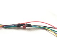
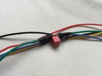
i built this circuit as a plug-between solution for my existing motor. unfortunately the local electronics shop hat only those big 63v caps with 6.8nF. so this could be a bit smaller. i will put all this in heat shrink and fill it with glue.

Foto 03.06.16, 17 22 28.jpg
Foto 03.06.16, 17 22 36.jpg
 
Good idea I think I will need to do the same!
 
I'm starting to wonder again about the effectiveness of this... am very curious about whether you guys notice the difference or not. I did measurements this afternoon and have the sneaky feeling the digital filtering I put inside the chip is more effective than the analog external.... for the same filtering bandwidth (read: phase shift penalty) I see better results with the digital filter. So please let me know your experiences !
 
Im going to start by adding shielded cable.
 
Lebowski said:
I'm starting to wonder again about the effectiveness of this... am very curious about whether you guys notice the difference or not. I did measurements this afternoon and have the sneaky feeling the digital filtering I put inside the chip is more effective than the analog external.... for the same filtering bandwidth (read: phase shift penalty) I see better results with the digital filter. So please let me know your experiences !
you tell me NOW!! ;) only joking. i hope weather will be ok, and my dc/dc will work again, so i can do some tests in the morning.
 
Back
Top