Game Changer Page 3 with video of 1700amps!!!!

toolbag said:
Have you looked at the loop inductance from that standoff layout? I started with something like that, but then I saw that the loop inductance from my loop (which was much smaller in area than what I'm seeing here) was an order of magnitude more than the ESL of the CAP :roll: .
This is version 1. Once perfected it will be much more optimized.

The cap was not my first choice but after building a big part of all of this I found these caps and with the next revisions I will both get the cap optimized for the controller and the controller layout for the cap.

Also remember the Negative (bottom where the longest lugs run) has 3 stand offs evenly spaced out and are all connected to the same plate so that cuts resistance and inductance down by 3x from just 1 stand off.
 
Some observations I made in my extensive parallel device research. High inductance in the DC bus = large turn off overshoot, some inductance in the MOSFET leads = good.

Study and understand the meaning Maxwells equations and the answers start to come naturally.

From what I saw in my testing, once the DC bus inductance > ~35nH at ~100V, the turn off overshoot becomes difficult to manage if you a switching speed < 1us is desired.
 
zombiess said:
Some observations I made in my extensive parallel device research. High inductance in the DC bus = large turn off overshoot, some inductance in the MOSFET leads = good.

Study and understand the meaning Maxwells equations and the answers start to come naturally.

From what I saw in my testing, once the DC bus inductance > ~35uH at ~100V, the turn off overshoot becomes difficult to manage if you a switching speed < 1us is desired.


WTF are you doing with 35uH on the DC bus?????

I am well aware of this I did very extensive testing on this a couple years ago.

As I say this design will be modified to work better with this cap design. But its still very good as it is... I all but forgot about the power ring caps untill I found these ones for a good price.

Next revision will cut DC link inductance down about 1/2 of this version or further. Remember a disc with power flowing out to all mosfets is uber low inductance.
 
Units were meant to be nH. Typo.

Once you can test fire you design, it is nice to know the layout inductance to help figuring out issues.
 
I maxed out the cap... :) But that's not a bad thing as when I plan to build HV Game Changer controllers for our EVs The cap will not allow enough current to flow to wreck the mosfets. :)
Now what I mean by that is during a short on time below 1000uS if there was a short the battery would most likely flow enough long term current to still kill them but desat is there to protect in both cases..

I am shooting for the moon with this controller so I will add more cap as the cap is what's limiting it. To prove that I will say the 440v DC breaker is only rated for 100 amps ;)

Non the less. I did everything I could today to get the power as high as I could I have the gates tuned fairly well and just a bit more will be good enough. I will see what I can do Monday and build up my other leaf boards and the other 2 stages for game changer and make it run a motor asap.....


[youtube]UHrsJUo5Tms[/youtube]
 
Did some more testing and worked on getting the switching cleaner above 1000amps. Made some progress but still a ways to go.

I found the current sensor is maxed out I thought I have seen over 1000 amps before but I must have been wrong. It seems to be stopping at about 1030amps.

I was able to use that and compare data with the voltage at the desat pin and test up to a estimated 1700 amps today. :)

[youtube]PxwBpWNFWV0[/youtube]
 
Nice!
 
Great progress!
How many fet's in parallel/what model? (sorry, didn't read thread)
 
okashira said:
Great progress!
How many fet's in parallel/what model? (sorry, didn't read thread)
8 ixfk230n20t I got them cheep and since I got them I have found better fets. but I am on a very tight budget so I will use them to prove the design :)
 
Arlo1 said:
okashira said:
Great progress!
How many fet's in parallel/what model? (sorry, didn't read thread)
8 ixfk230n20t I got them cheep and since I got them I have found better fets. but I am on a very tight budget so I will use them to prove the design :)

Cool.. Let's see how they do switching 1700 amps 1,000,000 times.
Those do look a little dated though so more modern ones should do even better.
We've been able to switch >3000 amps repeatedly with 6x IRF1324S-7P and 2.19 uH link inductance on the battery spot welder, but I am sure if we did it even at 500Hz they would blow up instantly :-D

I think you said you're at 15nH so you might be okay.
Once you get down to 5nH with your new board and bus barsand upgrade fets maybe 3000 amps at full PWM??? :-O
 
okashira said:
Arlo1 said:
okashira said:
Great progress!
How many fet's in parallel/what model? (sorry, didn't read thread)
8 ixfk230n20t I got them cheep and since I got them I have found better fets. but I am on a very tight budget so I will use them to prove the design :)

Cool.. Let's see how they do switching 1700 amps 1,000,000 times.
Those do look a little dated though so more modern ones should do even better.
We've been able to switch >3000 amps repeatedly with 6x IRF1324S-7P and 2.19 uH link inductance on the battery spot welder, but I am sure if we did it even at 500Hz they would blow up instantly :-D

I think you said you're at 15nH so you might be okay.
Once you get down to 5nH with your new board and bus barsand upgrade fets maybe 3000 amps at full PWM??? :-O
The plan is to test and get the switching clean up to ~1700-1800 amps then run it for 10sec bursts no higher then 1200 amps rms only if the system proves to be worth it.

Again. I have 70 of these fets sitting in stock. I do this as a hobby on my own dime while also working 60+hr a week to earn a living plus a bit for controller development. If you want to send some modern fets or money for modern fets. You can email transfer or paypal me :)
 
Looking again, they are not that bad actually. Really fast switching time for their size. Not used to looking at 200V MOSFET datasheets.
Then again, how much less conservative is IXYS on their datasheets compared to IRF?
 
okashira said:
Hmm, so you need 48 total, right? :-D
150V or 200V?
48pcs and the plan is to run a version with 150v rated fets on 28s and I'm also looking at 600 & 650v rated igbts to make a version for 98-112s :)
 
okashira said:
Then again, how much less conservative is IXYS on their datasheets compared to IRF?
I don't know but I do know I have proven IXYS parts to do what the data sheet said!

I like these ones... :) http://ixapps.ixys.com/DataSheet/DS100181(IXFK-FX360N15T2).pdf

And these 2 igbts parts....

http://ixapps.ixys.com/DataSheet/DS100518C(IXXK-X200N65B4).pdf


http://ixapps.ixys.com/DataSheet/DS100503(IXXK-X300N60B3).pdf
 
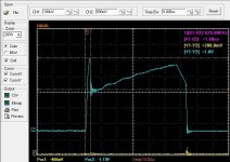
I now have the switching reasonably OK at 1750-1800 amp pulses.

It is a bit slow.... But it will be enough to test.

Blue trace is the Diff probe. Its x50
Yellow was not always hooked up as it made the blue trace look more noisy.
I need to get a second Diff probe. Yellow is x10
 

Attachments

  • crankedddd4.JPG
    crankedddd4.JPG
    71.7 KB · Views: 3,464
commenting to follow the thread, this is great i'd be happy to donate toward the dev
 
Awesome work Arlo.
"Kilo-amp club" has a ring to it.
 
Arlo1 said:
I now have the switching reasonably OK at 1750-1800 amp pulses.

It is a bit slow.... But it will be enough to test.

Blue trace is the Diff probe. Its x50
Yellow was not always hooked up as it made the blue trace look more noisy.
I need to get a second Diff probe. Yellow is x10

What is blue? current ?

let see turn on and turn off voltages at source drain
 
okashira said:
Arlo1 said:
I now have the switching reasonably OK at 1750-1800 amp pulses.

It is a bit slow.... But it will be enough to test.

Blue trace is the Diff probe. Its x50
Yellow was not always hooked up as it made the blue trace look more noisy.
I need to get a second Diff probe. Yellow is x10

What is blue? current ?

let see turn on and turn off voltages at source drain

Blue is voltages are D-S
I have to post newer screen shots. I did get it cleaned up a fair bit.
 
Always cool Arlo keep it up :)
sorry if its covered somewhere but in the hundreds of pages across all your threads i cant remember or find it.
do you know what the maximum/saturation current is into the leaf motor?
and any idea what torque that will equate to, Kt?

thanks
 
bj001 said:
Always cool Arlo keep it up :)
sorry if its covered somewhere but in the hundreds of pages across all your threads i cant remember or find it.
do you know what the maximum/saturation current is into the leaf motor?
and any idea what torque that will equate to, Kt?

thanks

https://endless-sphere.com/forums/viewtopic.php?f=30&t=65757

Kt the NM/amp seems to be about .466 but this is from extrapolating from data on the net.

I can tell you in the CRX I put it in it only takes 282.8 rms phase amps to make the tires break loose at speed.
And at 318 RMS phase amps it roasts the tires at speed. They are cheep tires for testing.... But it spins both of them!!!

Right now all the weight is over the front tires.!

As for a maximum current I measures a phase to phase resistance of .010 ohms SO I think its above 4000 amps. ;)
Likely you will quit making power before that.
 
ai! said:
thread is dead?
Nope.

I have been very focused on other projects Like getting the High Voltage hi power controller to Dyno the leaf motor over 300 hp at the wheels.

I will be back to this in time. Also have my first son 8.5 months ago and have been doing a lot of work for my own business!
 
Back
Top