Open Source BMS Project

Alan B said:
I don't think you'll see the motor at the BMS since the controller's cap bank is in the way.
Ok. I just noticed the MAX14921 is rated at 65V max (70V absolute maximum) - I had been thinking it was 60V - so I think it's best to use a 70-80V fet anyway so there is at least a bit of headroom when using the full range (e.g. 15S 4.35V Li-Ion)

Alan B said:
You'll see the wiring inductance when the BMS switches off. You might want to switch off slower. Going too fast is a liability. Good engineering will choose a turnoff rate that will mediate the various issues.
That makes sense. But would the controller caps not also protect against the wire inductance?

In the event of a short there are obviously going to be no high voltages caused by the inductance so in that case it would be best to switch off as fast as possible. I'll look at making a second driver to pull the gate low or something.
 
The high voltages during turnoff are generated by L di/dt. So making dt small when there is high current makes di/dt large. Depends how much L is in the loop as to how much voltage is generated.

The problem with measuring current with a shunt is the L/R time constant. Shunts are slow if you are looking for microsecond response when R is small, it doesn't take much L to slow it down.

Controller caps will shield against wire inductance beyond them, but from the BMS to the controller not.
 
Alan B said:
The high voltages during turnoff are generated by L di/dt. So making dt small when there is high current makes di/dt large. Depends how much L is in the loop as to how much voltage is generated.
Alan B said:
Controller caps will shield against wire inductance beyond them, but from the BMS to the controller not.
Understood

Alan B said:
The problem with measuring current with a shunt is the L/R time constant. Shunts are slow if you are looking for microsecond response when R is small, it doesn't take much L to slow it down.
Is what you're saying here that the wire inductance will smooth the current draw and thus delay the measurement of a short? Wouldn't any other type of sensor in the same location give the same results?
 
No, the problem is in the sensor's time constant, as I understand it, when you are looking at microsecond time scales. So it all gets back as to whether you want to make something that electronically can shut the FETs off prior to damage. I have not tested this myself, but it is periodically discussed here by folks building controllers if you search out postings by HighHopes and zombiess building his controller you'll see this type of discussion. You might want to do some testing, I don't think you'll be able to get this to work without building some circuits and testing them. Or you can go the simple brute force approach and put fuses or circuit breakers in, or tell the user to put the breaker externally. A BMS that will handle shorts with no big spark is nice however. Perhaps a shunt can be good enough, one thing depends on how much inductance is in the shorted path. The less inductance the faster the current will rise. The inductance helps by giving some time to shut things down, but it also stores energy it will feed back into the switch when it opens.

Here's a survey of current measurement technologies, but it doesn't get too deep.
http://www.oeco.com/wp-content/uploads/2015/01/Methods_Current_Measurement.pdf
 
Tesla uses shunt for the BMS (very fancy one) and Hall effect on the phase wires.
 
flangefrog said:
Can you give an example of a situation in which low/high side current sensing or fets would affect this?
I found an example of the problems here:
cell_man said:
A 2-wire BMS is best if you are planning to connect packs (each with a 2-wire BMS) in series/parellel. This is why we keep some 2 wire 7S BMS, built with 100V fets, so we could series up to 3 of them, but they'd still work like a single pack.

3-wire BMS in such circumstances can leave you open to possible issues WRT charging, and also means you couldn't connect 2 packs in series and charge them. This is because a pack could receive charge current through the discharge lead, after the charge circuit has gone OC.

For a single pack, with single charger, 2 or 3 wire will work just fine.
So the FETs will need to be rated for the full pack voltage. I don't want to do this by default as it's a big compromise but it could be worth having the option.

I haven't yet read the discussion on shunts, I'll do that soon. I will mention that my cheap 36V BMS with a shunt worked fine when I shorted it although it did still make a big spark. It may not be able to take it many times before the FETs are destroyed. From the small amount of research I've done on FETs the ones with the lowest Rds(on) seem to be able to take the most avalanche energy.
 
I've read the shunt discussion now. Some good info but they're talking about very high currents (with big shunts) and I'm not sure it would be a problem with the currents that the BMS will be primarily designed for. I'm hoping to make the BMS capable of 25A to 100A peak. For larger currents an external hall current sensor could be used instead.

What I understood from the discussion is that the L/R time constant over the shunt itself means the voltage measurement over the shunt lags behind the actual current flowing through the shunt. The time constant of the shunt should be much lower than the time constant of the whole circuit to be able to react quick enough.

Please correct me if my understanding or calculations are incorrect. Pretty much all I know about inductance is what I've picked up on ES over the last 8-10 months. I'll read up on the basics soon when I have some time.

The 1000A shunt inductance in the first post (50nH) and resulting time constant (1ms) seemed very high so I did some calculations based on one of the SMD manganin shunts I'm considering:

Shunt time constant
Shunt resistance: 0.2mΩ
Shunt inductance: <3nH
L/R time constant: 3nH / 0.2mΩ = 15μs

Circuit time constant
Example circuit consists of 2m 12ga copper

Wire resistance: 10.42mΩ
Wire inductance: 3.0079μH
Above based on https://ampbooks.com/home/amplifier-calculators/wire-inductance/

Battery: 14S4P 38mΩ cells
Battery resistance: 133mΩ
Battery inductance: ???

FET resistance: 2mΩ x 2

Total resistance: 10.42mΩ + 133mΩ + 4mΩ
L/R time constant: 3.0079μH / 147.42mΩ = 16.4μs
 
flangefrog said:
I've read the shunt discussion now. Some good info but they're talking about very high currents (with big shunts) and I'm not sure it would be a problem with the currents that the BMS will be primarily designed for. I'm hoping to make the BMS capable of 25A to 100A peak. For larger currents an external hall current sensor could be used instead.

What I understood from the discussion is that the L/R time constant over the shunt itself means the voltage measurement over the shunt lags behind the actual current flowing through the shunt. The time constant of the shunt should be much lower than the time constant of the whole circuit to be able to react quick enough.

Please correct me if my understanding or calculations are incorrect. Pretty much all I know about inductance is what I've picked up on ES over the last 8-10 months. I'll read up on the basics soon when I have some time.

The 1000A shunt inductance in the first post (50nH) and resulting time constant (1ms) seemed very high so I did some calculations based on one of the SMD manganin shunts I'm considering:

Shunt time constant
Shunt resistance: 0.2mΩ
Shunt inductance: <3nH
L/R time constant: 3nH / 0.2mΩ = 15μs

Circuit time constant
Example circuit consists of 2m 12ga copper

Wire resistance: 10.42mΩ
Wire inductance: 3.0079μH
Above based on https://ampbooks.com/home/amplifier-calculators/wire-inductance/

Battery: 14S4P 38mΩ cells
Battery resistance: 133mΩ
Battery inductance: ???

FET resistance: 2mΩ x 2

Total resistance: 10.42mΩ + 133mΩ + 4mΩ
L/R time constant: 3.0079μH / 147.42mΩ = 16.4μs

This is a total non issue ... you can ignore all that. you are not measuring some high frequency signal.
YOu only need to focus on good accuracy, ie a nice amplifier setup that allows you to use lowest resistance possible shunt and achieve good accuracy.
 
okashira said:
This is a total non issue ... you can ignore all that. you are not measuring some high frequency signal.
YOu only need to focus on good accuracy, ie a nice amplifier setup that allows you to use lowest resistance possible shunt and achieve good accuracy.
okashira, are you saying that the time constants etc are not important for short circuit protection? Or that I shouldn't be trying to add short protection?
 
flangefrog said:
okashira said:
This is a total non issue ... you can ignore all that. you are not measuring some high frequency signal.
YOu only need to focus on good accuracy, ie a nice amplifier setup that allows you to use lowest resistance possible shunt and achieve good accuracy.
okashira, are you saying that the time constants etc are not important for short circuit protection? Or that I shouldn't be trying to add short protection?
Sorry, I was thinking you were using for general current sense (ie for SoC calc)

But even for short circuit, if it's high inductance, so what, it will just make the signal even faster because the shunt terminals will see high voltage pretty quick.
Further, yeah, I think just a fuse is good enough, you risk blowing mosfets if you try to use them to switch short circuits.

Now that I think more about it, it may actually be desirable to have the shunt have high inductance for short circuit detection. This way it will pick up a high voltage even before the high current occurs - instead it can trigger on a excessive dI/dt event, and the mosfets can be turned off even before the excessive current occurs if you can make the system fast enough. :)
 
okashira said:
Sorry, I was thinking you were using for general current sense (ie for SoC calc)
I will be using it for this, but I'm looking at adding short protection as well if I can do it without any compromises.

okashira said:
if it's high inductance, so what, it will just make the signal even faster because the shunt terminals will see high voltage pretty quick.
okashira said:
Now that I think more about it, it may actually be desirable to have the shunt have high inductance for short circuit detection. This way it will pick up a high voltage even before the high current occurs
Can you please explain this in a bit more detail? What I understood (or misunderstood) from the discussion was that a high inductance shunt would smooth the current running through it and make the voltage across the shunt rise slowly.
 
It might be more productive to find examples specific to BMS short circuit current control. The voltage across the conducting FETs may be a better sensor.

A quick search turned up this paper, and I'm sure there are may others out there that targeted searching can unearth:

http://www.ti.com/lit/an/slua436/slua436.pdf
 
flangefrog said:
okashira said:
Sorry, I was thinking you were using for general current sense (ie for SoC calc)
I will be using it for this, but I'm looking at adding short protection as well if I can do it without any compromises.

okashira said:
if it's high inductance, so what, it will just make the signal even faster because the shunt terminals will see high voltage pretty quick.
okashira said:
Now that I think more about it, it may actually be desirable to have the shunt have high inductance for short circuit detection. This way it will pick up a high voltage even before the high current occurs
Can you please explain this in a bit more detail? What I understood (or misunderstood) from the discussion was that a high inductance shunt would smooth the current running through it and make the voltage across the shunt rise slowly.

The current flowing through the shunt will be exactly the current flowing though the rest of the circuit. Nothing you can do about that. (conservation of mass, Kirchhoff law, etc.)

If the shunt has inductance, then the voltage across the shunt terminals will be a function of not only the current, but a function of dI/dt. We can assume the shunt capacitance will be zero.

Further, we can assume the circuit that which the shunt is measuring current will have a very high inductance relative to the shunt itself. (battery lead length... etc.)

an inductor will show a high voltage if the dI/dt is high. So, a shunt with a high inductance will show a high voltage if the dI/dt is high.
Thus, a current shunt with a high inductance will display a high voltage (interpreted as a high current by the bms) during the time with the current ramps from zero to short circuit condition.

Thus, a shunt with high inductance will have no negative effect in terms of short circuit detection - in fact it may be able to detect short circuit before it actually fully occurs due to the high dI/dt that should occur during a short circuit event itself!

There may be negative end user effects due to this - for example if a poorly designed controller allows the user to ramp from 0 to 100% throttle without any damping. Or the system doesn't have any precharge spark suppression circuit, it could trigger the short circuit detection in this instance when there isn't really one.
 
okashira said:
The current flowing through the shunt will be exactly the current flowing through the rest of the circuit. Nothing you can do about that. (conservation of mass, Kirchhoff law, etc.)
I didn't word that correctly, I should have said the apparent current through the shunt (based on voltage measurements) will be smoothed. But I'm not sure if that's correct either.

After I've done some reading on basic inductor theory I'll come back to the short circuit protection discussion.

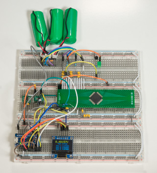
I received my TQFP-80 DIP breakout board from Proto Advantage today. After soldering the MAX14921, MAX11163 and MAX6194 I installed them on a breadboard and got the ADC/REF combo working. I'll try out the MAX14921 tomorrow.
 
flangefrog said:
okashira said:
The current flowing through the shunt will be exactly the current flowing through the rest of the circuit. Nothing you can do about that. (conservation of mass, Kirchhoff law, etc.)
I didn't word that correctly, I should have said the apparent current through the shunt (based on voltage measurements) will be smoothed. But I'm not sure if that's correct either.

After I've done some reading on basic inductor theory I'll come back to the short circuit protection discussion.

I received my TQFP-80 DIP breakout board from Proto Advantage today. After soldering the MAX14921, MAX11163 and MAX6194 I installed them on a breadboard and got the ADC/REF combo working. I'll try out the MAX14921 tomorrow.

There is no such thing as apparent current. Current is always real.
Something with inductance will display a high apparent POWER during a positive dI/dt event. This will be reflected as a higher voltage.
Thus, the shunt measurement will indicate a current higher then it really is during a current ramp up.
 
Could I make a suggestion, you could easily make this extreamly flexiable for larger series/parallel battery banks by having the ADC, Ref and MAX14921 and balancing circuits on pcb's with their data lines galvanicly isolated so that you could easily add more banks of 16 BMS channels in its most basic form it can be exactly as you are already designing with a MAX14921, mpu ect, but then you could add more if required, that would be really useful! Especially as you could have any combination of S/P and the BMS wouldn't care.
 
ChrisPRoberts said:
Could I make a suggestion, you could easily make this extreamly flexiable for larger series/parallel battery banks by having the ADC, Ref and MAX14921 and balancing circuits on pcb's with their data lines galvanicly isolated so that you could easily add more banks of 16 BMS channels in its most basic form it can be exactly as you are already designing with a MAX14921, mpu ect, but then you could add more if required, that would be really useful! Especially as you could have any combination of S/P and the BMS wouldn't care.
I did consider this but it requires several compromises when using it for only 16S:
Using two PCBs would increase the size and production cost.
To keep the current draw constant across all cells a voltage regulator would be needed on the main board that can cope with the full pack voltage. More than 120V = limited choice and increased cost.
Low power capacitive or magnetic isolation ICs are expensive. If using Maxim parts two MAX14850s would be needed.

What I am still considering is having a main board with logic and 16S support and allowing another 16S expansion board(s) to be plugged in.

It may just be better to allow two separate BMSs to be used on each pack half for 32S as that way the packs can also be used separately.
 
I got the MAX14921 AFE working today. I couldn't get it to respond for a while but then I found the enable pin was connected to an unused power rail.

The pack voltage measurement from the AFE's internal voltage divider isn't as accurate as I expected but it is just within the +2.5% spec. It's much more accurate to get the total pack voltage by adding up the cell voltages.

With the logic/display powered fully off the battery I'm getting very inaccurate readings (e.g. ±200mV) and sometimes the cell voltages drop to 0V. I haven't checked what's causing that but I think it's something around the ADC.
Edit: the problem was bad grounds (because of the breadboard) and noise from the 7805 (OLED draws a lot of current and I don't have the right filter caps ATM). I looked at it with an oscilloscope and I was surprised how much cleaner the USB power from my PC was.

I have manual balancing working for one cell using an LED instead of a resistor.

 
Do you plan to set up some repository for this project?
I'm going to design a single board 8s BMS for a mobility scooter around MAX14920 AFE + AVR. I'd like to make it as a contribution to opensource project rather then to reinvent a wheel. BTW, I'm skilled PCB designer and I prefer SMT components.
 
ctirad said:
Do you plan to set up some repository for this project?
I'm going to design a single board 8s BMS for a mobility scooter around MAX14920 AFE + AVR. I'd like to make it as a contribution to opensource project rather then to reinvent a wheel. BTW, I'm skilled PCB designer and I prefer SMT components.
Sorry for the late reply. Yes I will be setting up a repository on GitHub but I will probably only start working on the production code once I have finalised the hardware. I'm ready to start work on this again soon and I feel I understand inductance better now. The spot welder threads especially have given me some ideas on how to implement short protection in the BMS.

I don't yet have any experience laying out PCBs so I could certainly use any help I can get when I get to that stage. I'm planning to use KiCad for both the schematics and PCB layout.
 
Back
Top