The "thermal management of LiPo" thread!

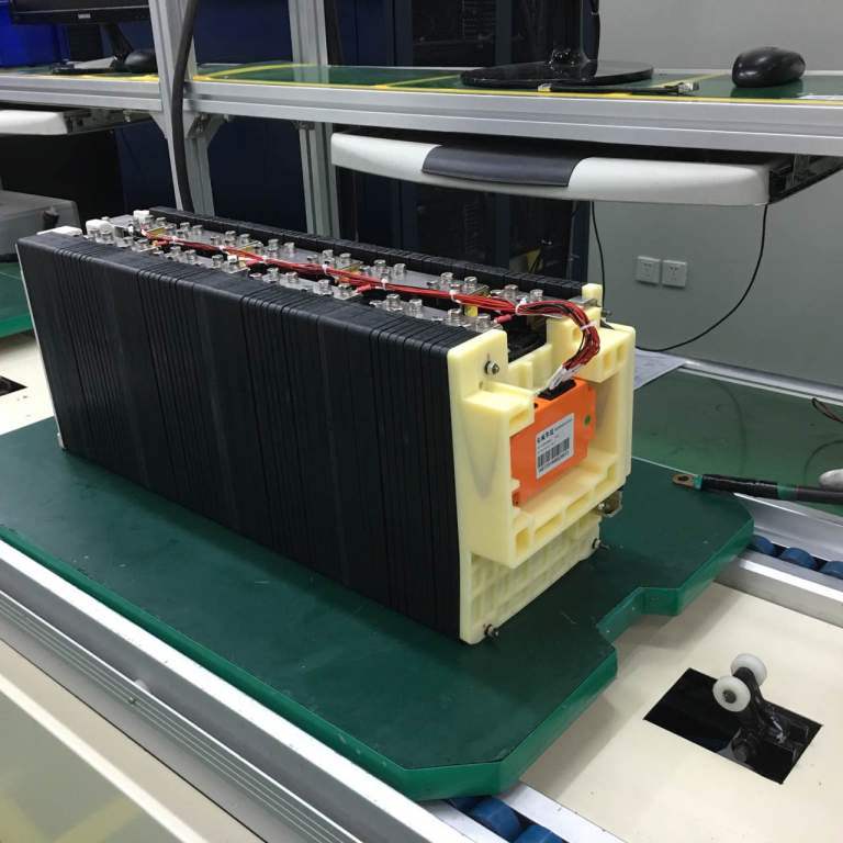
Pouch cells conduct heat well from the edges. Its like 20% Cu/Al solid through that plane.

Clamp them well and give a short and low Rth path to ambient from all edges you can. 3 edges is very possible, the 4th is more difficult with the tabs, but all the open space around a high current density and high temperature region of cells for ducted forced air to work well.
 
Which is why I think passing air over the conductors would work reasonably well. Unfortunately I have to cover them for electrical isolation reasons (the BMS wouldn't last very long if I plopped it down on the copper :lol:) but even removing the boundary layer of warm air will serve to cool the copper which in turn wicks heat out of the cell.

Compression helps keep the heat transfer path short, but it also helps limit any movement among cells. Seems physical trauma is the most common failure mode after overcharge or overdischarge.

I'll have to see if Entecho wants to make the second battery test pack an experiment in thermal management...
 
Placing some small thermistors in various spots on the pack with some kind of datalogger would be an excellent way to evaluate different approaches.

If your packs are surviving in a totally sealed environment now, I don't think you will need a lot of air to keep them really happy.

On my forced air cooled scooter motors, I located the blower inlet inside the covered (but vented) battery compartment so it did not pick up any water when riding in rain. There's usually somewhere under a panel on a motorcycle that you can pick up air without getting rain or debris.

I see the point about cell orientation. The edges may not be as thermally conductive as the flat side. I suspect thin aluminum plates between cells won't do much if the thermal conductivity of the battery plates is already pretty good. I wasn't too sure about that, but what Luke says makes sense as the cell is really a stack of metal plates to begin with.
 
Yes and no - the flat face of the cell is where the heat ends up being accessible, and it's this heat we wish to remove. We can't blow air across the cell's face when there's a hundred of them all stacked cheek by jowl. You can blow air across the sides of the cells (folded edges) but the better path would be to conduct that heat out of the cell by means of a thin ally plate and at the end of that plate, have an extension which serves as a radiator. Heat will move where there is a 'potential' difference, so provided the radiator end of it is cooler than the cell face end, it will get 'pulled' out.

This works where you have the room for it, but when you don't, you end up relying on the thermal conductivity of the battery enclosure, which given it needs to be non-conductive, isn't very good. A series of holes to 'aerate' the pack would be a good compromise, provided the holes were protected at some point by a baffle plate from road debris, grit and water.

The BMS modules on top of our battery packs have two thermisters each, so there's room for a bit of datalogging. We really need to work out how fast the pack gets up to temp, and how long it stays there. I'm a big fan of the polycarb box, but the boss hates it - too heavy. I've no doubt that a fibreglass enclosure could be made which does the same thing.
 
This idea would be to insert a layer of 0.2 mm aluminium sheet between each cell. The sheet would need to be coated in some heat conductive, yet foil pouch sensitive surface, so no fretting or chaffing can occur.

cooling fins.jpg

The basic idea is that as the cells heat up, the aluminium will soak up the heat. The cooling fin on the outside is able to re-radiate that heat, and depending on its orientation take advantage of convection or forced air. If you wanted this idea to be remotely useful you would have to put it inside an enclosure which has forced air, although you could always cut sick with a caulking gun full of silicone goo. The holes allow for 5 mm threaded rod to be put through the pack and a pair of aluminium plates could complete the compression.

Some obvious flaws are that there is a conductive metal pressed up against fragile cells, risking a short in the event of chaffing. Also, the fins limit the placement options to vertical, or flat on their face provided air could be blasted around it.

More stupid ideas to come, but I look forward to comments!
 
This idea is far more complicated, heavy, and expensive. It takes up valuable battery space, but it also stands to do a darn good job of removing the heat. I have no idea how you would attach the 0.2 mm aluminium sheet to the aluminium block in the middle which has a cooling loop, but if you could ensure a good bond, then it would be a matter of slipping the built pack through the fins and clamping firmly as before.

cooling block.jpg

I put one 'fin' every two cells, but you could do every third if you wanted to. One per cell would be a bit over the top I think...

At least this pack could be rendered waterproof by placing the whole lot into a sealed enclosure.
 
The upper drawing looks like what I've seen others do. The thermal resistance of the cell itself from the middle of a cell to the outer edge is probably lower than what you'd get out of a thin aluminum plate, but it would allow a path from the flat side to the fins that's pretty short near the edge. The thickness of all those plates will add up, as will the weight.

Since the heat should be able to travel well from one cell to the next, using plates on every other cell might be adequate.

Something like peel-and-stick Kapton tape would be good insulation for the plates (but expensive). Good hard anodization or even epoxy paint might be OK. If the cells are compressed, there shouldn't be any chafing. If they are coated, you'd need a failure on both sides before it really becomes a problem.

If you drilled a bunch of holes in the fins, you might be able to pack it tight in the box and blow air through the holes.

In the lower drawing, I don't think the big block will help, and as you point out would be difficult to fabricate.

My guess is in this application, most of the heat is going to be generated on the terminal end of the cell. All the current is concentrated there, so most of the resistance heating will occur there. You already have nice thick copper bars attached to the tabs, so simply blowing air over the interconnections might do a pretty good job.
 
the cells are already packed into aluminum foil, i fail to understand what is to be gained..

If you could clamp onto the pouches sealed edges only *( would require pulling them out straight, should be fairly easy ) but then you prevent a puffing cell form bursting the seam if need be so something else would have to give ( likely at the top of the cells between the terminals )
 
Ok, I seem to be missing part of the equation.... :oops:

How many cells are you using?
What are their dimensions?
What is the maximum allowable battery area you can tolerate?

:D
 
e-beach, I'm typically building blocks of 24 to 42s and 3p, but I also have 4p and 5p boards for 20 and 25 Ah packs. So there is a lot of cells in each pack, and they are currently stuffed tightly together in the most space efficient means possible.

They will get warm during discharge, and they can get quite hot during discharge. What I don't know is a) whether this is a bad thing, and b) whether some kind of cooling system will give performance gains worthy of the weight/space cost.

Basically, if OEM battery packs are coming out with cooling, there is clearly some merit to it. But I also believe that if it adds significant weight and volume to a pack, a slightly larger pack would probably achieve the same end.

Gaston, the foil pouches are better placed to have their heat conducted away from them by means of a direct contact to the face than from the edge of the cell. That's the idea with the plates anyway. I have another idea I'll draw up soon which follows on from the different orientation of the cell groups.

I'm not the only source of ideas around here - get drawing guys! :D
 
jonescg said:
.......I'm not the only source of ideas around here - get drawing guys! :D

Can't wrap my mind around it anymore without dimensions..... :(

I could draw up a really nice design to cool your pack, but if it won't fit your space, why waste the time. But, if you give us something to work on like a specific size of the cells, how many cells and how big a space you want to put it into,......it could get my brain working a bit harder. :lol:

Start off with your most powerful pack desired. How many cells, cell detentions and the maximum space it can occupy

:D
 
e-beach, if it helps, we'll aim for a 28s3p pack. It ordinarily occupies 378 mm by 100 mm, and stands about 150 mm tall.

And yes, this is all academic. I'm looking at what gains there may be in cooling a big LiPo pack. If you keep it under 10C, I can't see a need for cooling whatsoever, but after the flight test packs were giving about 58'C after two hard cycles, I got to thinking about what cooling might offer.
 
Ypedal said:
Ebeach. This is theoretical and applicable to any pack. :wink:

Well,(in my best Stan Laurel imitation) if it is theoretical, how about a how about a 1 foot (30 Centimeters) gap between each cell so ice cubes can be stuffed into the gaps. Of course the ice will be provided by the ice making machine being pushed in front of the motorcycle..... :roll:

Ok, sorry for being facetious, but I think that the dimensions are still critical.

If you seriously want to cool a battery under heavy c's, then the only logical way is to expose as much of it's surface area to a cooling air flow, whether it is from a fan or from forced air as in a scoop behind the front wheel that directs air across the battery.

Providing you don't want to power Peltier cooling pads sandwiched into the packs or something more exotic.

To be able to design a cooling system for the application, one needs to know the specifics of the application or the ice cube machine it is. :lol:
 
China battery maker getting into the act...

"Electric Car Pack with Liquid Thermal Management System":
http://www.made-in-china.com/showro...ck-with-Liquid-Thermal-Management-System.html

Electric-Car-Pack-with-Liquid-Thermal-Management-System.jpg


"FOB Price:US $4,000 / Piece"

Rate capacity 300Ah
Nominal voltage 18.25V
Discharge cut voltage 16.5V
Charge cut voltage 20.75V

Interestingly enough... or not... "Beijing Huate Electric Technology Co. Ltd" not mentioned in ES Bible... `til now.
 
I don't know if it's an image artefact, but that plastic compression plate on the end of the pack looks comically bent! :lol:
 
It's hard to imagine a heatsinking system, that won't be impractically large or heavy. If you want thermostatic a phase change could do it - but I can only think of something like paraffin wax - this turns out to be pretty good, specific heat capacity 2500J/kgK (that's excellent, over half as good as water) and latent heat of fusion is 200kJ/kg.
It would make any fire a good deal worse but you shouldn't need a lot of it....
for comparison the specific heat capacity of lead is 125 and Al is 921
What do you think about dipping your cells in a tub of molten candle wax......???
I guess the safety concerns should be about as significant as the oil in an ICE
 
The 28kWh Xalt pouch cells in the Formula E race cars are liquid cooled by immersion in a sealed battery pack.
Packs are designed and built by Williams Engineering in the UK.
http://www.fiaformulae.com/en/news/2014/september/the-formula-e-battery-a-qa-with-craig-wilson.aspx
 
jonescg said:
This idea would be to insert a layer of 0.2 mm aluminium sheet between each cell. The sheet would need to be coated in some heat conductive, yet foil pouch sensitive surface, so no fretting or chaffing can occur.
View attachment PGS_Br.pdf
http://www.digikey.com/product-deta...ronic-components/EYG-S091310/P11439-ND/429230

More stupid ideas to come, but I look forward to comments!
those are the most entertaining.
all your openly shared & intellectually honest work (rather than stoopid) is definitely appreciated.
pls don't hold back because of the great unwashed conventional thinkerz out there.
 
Wow, that PGS stuff is amazing. Datasheet says up to 5x more than copper. This could have applications in motors and controllers as well as batteries.
 
Huh. Wonder why a company like Panasonic might be interested in this stuff [cough cough]:
High_Thermal.jpg
 
I done a backyard experiment and placed my lipo cells in aluminuim plates sprayed black they always feel cold to the touch now I think this restricts charging with the cell being cooler I get 10% less wh stored and my c ratings have dropped to half, After my ride the block of lipo is barely ambient temp so I'll be trying out a new approach soon.
The best method would be to compress the face and maintain a steady 20°c, more of heat management than flat out cooling.
 
Back
Top