E-Street Machine 20kW

madin88 said:
when installing tires, i personally inflate maximum pressure (for making the tires sitting correct), and than i deflate to the pressure i like to have.
it also may help if you spray soapy water on the rim and rubber (for lower friction).

what rim do you have?

I have a 19x1.4 motorcycle rim from treatland.tv.

Wheazel said:
The first picture looks correct. Have you tried to deflate and reposition the tyre to climb a little higher in needed areas?

I inflated the tire to about 50 PSI (rated for 34) and at some point along the way the tire seated correctly with some dish soapy water. Deflated back to 28 and everything looks good. Thanks for the tips.
 
ninepointeight said:
From what I understand, the Electric Enduro Ebike frame comes with plastic molded side panels, as opposed to the vector frame with aluminum(?) side panels. The plastic molded side panels actually extend out past the frame, bringing the width to 140mm.


Cabbage! Nine I saw just now that you answered me! Sorry about that shame ... :oops:
Actually, the thermoformed panels I have taken extend beyond 140mm, and I should make it all; Intermediate separating panels, nickel strips and so on.

I meant how you did it because you did not have the extended skirts and therefore are equal to the end of the chassis. I honestly did not understand how many others have succeeded in entering two rows of cells side by side with flat normal panels. Mah! For me it's a mystery
 
It lives!
I finally got everything* put together and took it for a spin. The suspension feels amazing, and at the minimum power settings (20% phase current, 20% battery current, about 1500w) it feels still powerful at low speed, more than enough torque to power up right onto curves. The Shimano Zee front brake I got doesn't seem very powerful, maybe I am still in the break in period. Even at full pull it doesnt seem to have near enough power to stop the bike as I would expect it to. So for the mean time, no danger of a OTB incident. I haven't installed any arduino or neopixel instruments yet, because I was too excited to put it all together.
Charging it for the first time tonight...
 
Hey that's awesome! Get her up to full power!!

Question on the charger since the website has next to no info. Does it spit out whatever voltage you reequest over CAN, or what? I want one of those they're powerful and inexpensive.
 
great project! i wish you best of luck!

couple of hints-
be very careful about the type of silicone you use- neutral cure MAY be ok, but the aetic stuff? keep it the hell away from anything copper, maybe nickel too, even the fumes corrode things.

another hint, hotglue ca be easilly removed with metholated spirits, which breaks the bond
It looks like it too late for these hints anyway :lol: but it could be good to temporarily hotglue the pack to the frame to keep it from shaking about

last hint, dont trust the chinese steel dropouts one iota to hold up to the 273!
you will need to weld on some extra clamping sections to make it work id say..
 
flat tire said:
Hey that's awesome! Get her up to full power!!

Question on the charger since the website has next to no info. Does it spit out whatever voltage you reequest over CAN, or what? I want one of those they're powerful and inexpensive.
I took it up to half phase current, so 275 amps, and wow it pulls.
I did not select the can bus version, however if I knew I could change the voltage by sending a reference down the can bus, I would have. Idk about inexpensive, almost $300. But for the power it's nice. It does not seem to be user serviceable, many components are bolted to the side of the case for heat sinking, so I don't think changing the voltage is in the cards any time soon.
 
ridethelightning said:
great project! i wish you best of luck!

couple of hints-
be very careful about the type of silicone you use- neutral cure MAY be ok, but the aetic stuff? keep it the hell away from anything copper, maybe nickel too, even the fumes corrode things.

another hint, hotglue ca be easilly removed with metholated spirits, which breaks the bond
It looks like it too late for these hints anyway :lol: but it could be good to temporarily hotglue the pack to the frame to keep it from shaking about

last hint, dont trust the chinese steel dropouts one iota to hold up to the 273!
you will need to weld on some extra clamping sections to make it work id say..

Thanks for the advice, I thought those fumes we're pretty strong. I only used it to glue the batteries together so I think I'm good.
As for hot glue, there is absolutely no movement of the packs. They are in there so tight I could barely get the side panels on.

As for the dropouts, I will probably just have some steel bar stock milled to fit the axle and bolt it to the frame, no welder :(. But for the time being I have only got it at half power and that is scary enough for the time being.
 
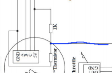
I do need some help in regards to the motor temperature sensor. I tried connecting it in the manner that the KEB manual states, with a 1kohm resistor between the lead and the 5v signal, measuring in between, illustrated by the blue line in the picture. But when I did this I got a hall short error. Is this resistor to 5v already inside the motor?
foai.png

Also, after riding it for a while, it is painfully evident to me that even without a temperature sensor installed, the side covers become warm after flogging it a few times. I can't image what the winding temperatures are, but I am looking into a cooling solution, so it is either ferrofluid and maybe hubsinks, or EDF cooling, so if CowardlyDuck or Offroader is reading this, please feel free to recommend a solution, but I am leaning towards ferrofluid + hubsinks, because I don't feel like stuffing more wires down that axle, and also installing an ESC and the right power for that.
 
I enabled regen when off the throttle finally, and was getting used to it, however when switching from high power to regen there is a loud noticeable thud in the axle. The axle seems to move the outer portion of the dropouts, and no amount of tightening those bolts will keep it in place. Only the outer portion clamps, which is a pretty major design flaw IMO. They should both have clamping bolts. There is a video below that shows what my problem is here. Advice and suggestions are welcome. Starts at 52 seconds in.
https://youtu.be/3azHFG_9Y-c?t=51
 
ninepointeight said:
I enabled regen when off the throttle finally, and was getting used to it, however when switching from high power to regen there is a loud noticeable thud in the axle. The axle seems to move the outer portion of the dropouts, and no amount of tightening those bolts will keep it in place. Only the outer portion clamps, which is a pretty major design flaw IMO. They should both have clamping bolts. There is a video below that shows what my problem is here. Advice and suggestions are welcome. Starts at 52 seconds in.
https://youtu.be/3azHFG_9Y-c?t=51

better sort this BEFORE you break the dropouts and possibly an axle, shread the cables, short phases/blow controller, and above all,have to walk home :|
the bike needs some serious clamping torque arms. it would be worth your while getting them laser cut and sent to you, then weld them onto the frame.

id suggest dr bass torque arms, but they arnt clamping and therefore not really suitable here.

if you continue to roll the axle flats in the drops, it will round your axle and stuff it for good :wink:
 
Get rid of the regen unless you can make it super soft but then it's nearly worthless in my opinion. At best you will get 5% back if your in a super hilly area but with that much mass spinning rocking your axle/dropouts your pretty much assured to one day take the walk of shame home.

My $.02!

Tom
 
ridethelightning said:
ninepointeight said:
I enabled regen when off the throttle finally, and was getting used to it, however when switching from high power to regen there is a loud noticeable thud in the axle. The axle seems to move the outer portion of the dropouts, and no amount of tightening those bolts will keep it in place. Only the outer portion clamps, which is a pretty major design flaw IMO. They should both have clamping bolts. There is a video below that shows what my problem is here. Advice and suggestions are welcome. Starts at 52 seconds in.
https://youtu.be/3azHFG_9Y-c?t=51

better sort this BEFORE you break the dropouts and possibly an axle, shread the cables, short phases/blow controller, and above all,have to walk home :|
the bike needs some serious clamping torque arms. it would be worth your while getting them laser cut and sent to you, then weld them onto the frame.

id suggest dr bass torque arms, but they arnt clamping and therefore not really suitable here.

if you continue to roll the axle flats in the drops, it will round your axle and stuff it for good :wink:

litespeed said:
Get rid of the regen unless you can make it super soft but then it's nearly worthless in my opinion. At best you will get 5% back if your in a super hilly area but with that much mass spinning rocking your axle/dropouts your pretty much assured to one day take the walk of shame home.

My $.02!

Tom

Thanks for the advice. I want to keep the regen if possible, because it is a very heavy bike and I am sure I would eat through mtb brake pads quickly. I am going to go buy some 1/2" x 2" steel flatbar tomorrow and have it laser cut. On the ends I am going to drill and tap it so a block can bolt on to the other side of the axle. 2 bolts per block on each side of the axle so I can tighten it properly, with nice flat sides. I still don't have access to a welder though so I may have to bolt the arm to the frame. I will be removing the crappy bolt on bits that came with with the frame in lieu of this.
 
sounds like a good plan. if you can get the attachment point where the TAs attach to the swingarm ~8 inches from the dropouts, the force on the bolts there wont be so great
but id still use m8 bolts there.

-make sure the design allows for the clamping dropout to pinch slightly, grabbing the axle. if not, there may be a tiny discrepancy between axle thickness and the width of dropout allowing for movement, ie. back where you started, unless you want to mess about with copper shims :|
id go 8mm bolts to tighten the dropouts if pos, but 6mm might be ok.

this is critical when using regen on a big bike. if you get it right, using regen should be fine.

the qs205 has a large flat section on axle shoulder on one side which i took advantage of and made the dropouts to grab that also. if the 273 also has this, id use it :wink:
 
This is what I had in mind, none of this is to scale, i just did this in a few minutes to visualize my idea. http://imgur.com/a/7IMcT
img8.png
img6.png
img7.png
img5.png
When I get it welded/bolted I will make sure the long part is flush pressed against the axle, and then attach it. After that I will bolt on the outer block so that it doesn't pull or bend the axle, only compress it. I am using half inch steel. The only problem possibly is the space between the frame's dropout and the added dropout. Basically I am clamping further down the axle, which is not ideal, but the solution involves welding another chunk to the end of the main bar, but keeping the dropout side perfectly flush against the axle, which just adds complexity.
 
welding the extra chunk against the bar would be good, that way you could have ~1" of clamping contact on each end of the axle, using 4 smaller bolts at each side.
that is the sort of respect id be giving a qs273 :lol:
 
I will be going with the 1 inch wide clamping section on the axle, even though it is 2 extra welds for whoever has to deal with my stingy ass.
Got the steel and used part of the long arm sections to test a drill and tap 3/8" NC, because i have never drilled or tapped in steel before. Took about 20 minutes, but patience makes perfect, or something like that. Looks good and feels good, now I have 8 more to do, but for real.
 
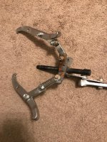
It has been quite a while as I have been very very busy, but I'm back. I am currently in the process of taking apart my motor to add ferrofluid and spray varnish inside. I am having a lot of trouble opening the motor and could use some help. I have taken off the bolts on the wire side and I am attempting to separate the motor. I undid the bolts on the wire side and have it opened about a centimeter but I don't know how to get it any farther. I don't have a 3 jaw puller that is big enough. Should I use wedges bigger and bigger until it comes out? Anyone opened the 273 or 203 could shed some light?

Thanks
 
ninepointeight said:
It has been quite a while as I have been very very busy, but I'm back. I am currently in the process of taking apart my motor to add ferrofluid and spray varnish inside. I am having a lot of trouble opening the motor and could use some help. I have taken off the bolts on the wire side and I am attempting to separate the motor. I undid the bolts on the wire side and have it opened about a centimeter but I don't know how to get it any farther. I don't have a 3 jaw puller that is big enough. Should I use wedges bigger and bigger until it comes out? Anyone opened the 273 or 203 could shed some light?

Thanks
The wedges wont hurt, i opened hubs much bigger than the 273 that required a lot of effort to separate.
 
ninepointeight said:
It has been quite a while as I have been very very busy, but I'm back. I am currently in the process of taking apart my motor to add ferrofluid and spray varnish inside. I am having a lot of trouble opening the motor and could use some help. I have taken off the bolts on the wire side and I am attempting to separate the motor. I undid the bolts on the wire side and have it opened about a centimeter but I don't know how to get it any farther. I don't have a 3 jaw puller that is big enough. Should I use wedges bigger and bigger until it comes out? Anyone opened the 273 or 203 could shed some light?

Thanks

i recently opened mine with a 3 jaw puller,if your 3 jaw puller is held together by two rectangle looking spacer with holes drilled on it for the bolt to go in,you can unloosen it and re extend the feet of the jaw puller
 

Attachments

  • 3 jaw puller.jpg
    3 jaw puller.jpg
    174.7 KB · Views: 3,265
I did get the hub open, using nothing but wooden wedges and a rubber mallet. I don't have a gear puller, although next time, I might buy one :? . I then sprayed varnish on everything internal, and added about 8.5 ml of ferrofluid, and i finally added my arduino + neopixel display that reads out power and motor temp, although the -300A to 300A hall effect power sensor (ring) walks around about + or - 5 to 15 amps which makes readouts kind of strange. In another iteration I would definitely use a shunt instead.

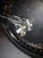
I finished(?) my new axle clamps and they seem very tight, however occasionally in normal use (and always when I use regen braking) I can hear a click from the axle the same as before from the axle rocking back and forth. Pretty disappointing, considering what I built to fix this. Still, it is an improvement and I would do it again, it certainly gives some peace of mind. I will upload more pics in HD if anyone wants to see. There is no visible gap between the axle and the clamps.

smallIMG_20171212_175642116.jpg

I will also later upload pics of the arduino computer and possibly a video, if anyone wants the code let me know and I will upload to github. It looks like a real mess (code and computer) but it works and is sturdy enough.

I only have to charge it once or twice a week riding at least 10 miles a day, and I never have range anxiety. Also I havent managed to get the motor up above 50 degrees c but I am sure that will change because it is about 10 degrees c where I live, so in the summer it should do just fine.
With the new clamp setup I took it out at full power for the first time ever and its insane. I can power wheelie at 25+ mph and it is insane all the way. I am sure I could have a somewhat similar experience with a higher kv motor but with a top speed of 55mph right now I am glad I went with what I did, I almost never go that fast.
 
FlyingFinn said:
I will copy your battery & frame setup but build it around this: https://m.aliexpress.com/s/item/32833606402.html?spm=a2g0n.search-cache.0.0.6293665drUYGul

What do you think? Controller pure rubbish? 21” 2.75 moto tires are a must. I will bolt the cycle satiator on top of outside of the frame for an easy on-the-go charging. Definately will change the brakes to Tektro E-brakes with 203mm rotors.

Never seen or used a controller like that, but I can't imagine it is of high quality, considering the price of the whole setup, but it might just do the trick for 8kw. TBH I would consider the controller a backup, but that depends on how reliable you need your bike to be.

I would not copy my battery and frame setup unless you plan to use the batteries to their maximum output, and depending on your cell choice, I don't think 8kw is going to do it. There really is no other reason for having 60lbs of battery under you, unless you are trying to do long distance (100 mile+) commutes. Also it was a huge PITA getting everything to fit, the battery left almost no space for anything else.
 
ninepointeight said:
Never seen or used a controller like that, but I can't imagine it is of high quality, considering the price of the whole setup, but it might just do the trick for 8kw. TBH I would consider the controller a backup, but that depends on how reliable you need your bike to be.

I would not copy my battery and frame setup unless you plan to use the batteries to their maximum output, and depending on your cell choice, I don't think 8kw is going to do it. There really is no other reason for having 60lbs of battery under you, unless you are trying to do long distance (100 mile+) commutes. Also it was a huge PITA getting everything to fit, the battery left almost no space for anything else.

Thx for your answer! Yes there is a real reason why I’m planning to install this monster battery. I have 145kms to my summer cottage and planning to drive up there occasionally besides the normal city commuting. EU directives state that e-bike max speed is 15 mph so planning to use backroads where I can blast a little faster with no cops in sight.

Car ownership in Finland is crazy expensive. 2k$ a year for the bare fixed expenses and on top of that gas is 7.5$ per gallon.

I’m planning to install there about 450 Sanyo GA cells which are 3.5Ah each. That would bring me a range about 220km/135 miles.
 
Back
Top