Switched Reluctance Motors

Hmm a quick googling gave various chinese SRM's. From 2kw and upwards >300 kw.
What I could see was that they all was 300+v motors. I guess not really suited for LEV.

But I do see advantages of dropping the magnets. It should be possible to make more power for less money with the SRM vs BLDC PM. Also no magnet overheat.

Stator and axle is spinning while the motor shell is stationary? So cooling by axle mounted fan or even in tandem with LCS cooling jacket?
 
Synchronous machine on sinus nourishment in our university department has been fully tested. More than 76% of the efficiency from it is not obtained. In our engine, the theoretical efficiency can be 98%. We reduce the moment ripple by increasing the phases. And the mass of the wheel motor is very large. On my motor SRM (for Cessna 152) 66 kW rated power 120 kW maximum. Also 4 phases but 12 poles. We get 300NM 2700rpm. Also I have a three-phase machine of 2400 rpm. 3 kW for helicopter or copter. But you need another steel for 600-800Hz.

[youtube]X_SOpAazsP4[/youtube]
 

Attachments

  • 2017-05-11_22-46-48.jpg
    2017-05-11_22-46-48.jpg
    115.9 KB · Views: 4,137
  • 2017-05-11_22-47-21.jpg
    2017-05-11_22-47-21.jpg
    83.4 KB · Views: 4,137
  • 2017-05-11_22-48-29.jpg
    2017-05-11_22-48-29.jpg
    150.7 KB · Views: 4,513
  • 2017-05-11_22-48-09.jpg
    2017-05-11_22-48-09.jpg
    174.1 KB · Views: 4,513
bobc said:
They are intermediate between IM and BLDC/PSM in efficiency but should be cheaper than IM to make, which is why we were interested,..

Thank you for your input Bob, it's great you've got experience with them and I appreciate you sharing it.

I would like to respectfully disagree they have some inherent efficiency disadvantage though. I happen to have a client with an SR drivetrain that's just over 96.5% including controller losses in a running prototype.
 
MMtech - sorry for littering your thread about your mighty motor with ramblings about synchronous reluctance motors, it was a response to lebowski that got out of hand......
everyone else - SRM can stand for "synchronous reluctance motor" or "switched reluctance motor". These are very different beasts, and both are, or will soon be, important motive powerers!
 
file.php


looks like a beast
 
The Finnish company "Visedo" has developed a prototype SR motor that they claim has minor improvements over previous designs (a hybrid SR plus permanent magnet configuration, "SRPM"). They are developing large motors for city buses, boat-ferry's, etc. Based on the performance of the prototypes, they have raised a lot of money for expansion...

150-kW/650-kW, liquid-cooled

In the motor by Visedo, I am very impressed by how large the hairpin copper-bar coils are, fairly easy to replicate in a garage, using laser-cut steel to assemble a stator. (it sounds like the poles in an SR motor don't change magnetic orientation, so laminations are not a requirement, I just meant that the stator is so thick, it would be easier to order sections that we rivet together)
 
If self-starting isn’t required (which I would argue is the case for ebikes) would single phase not have some benifits for SR hub motors?

I’m a total noob but I was wondering, would you not get better power (utilizing all poles at once), more balanced forces for less vibration and noise, and simpler switching?
 
This seems to be the largest thread for "Switched Reluctance" on ES. So rather than start a new thread, I'd like to park some info I found on SR motors here...
 
Ha ha! I am at work, and I'll post the references and pics soon. I have limited options from my ancient smart phone, and the desktops at work are also very restricted as to what I can do on them.

LFP mentioned in a thread a short while ago that Switched Reluctance (SR) is where the big players are putting their R&D money and time. SR has been around since the late 1800's, and modern low-speed stepper motors are SR, so their basic principles are well known. Why now? It's because of cost and performance in the controllers.

This last ten years, solid state electronics have advanced, and also gotten cheaper. The benefits as I see them are...

A. Trade war with China, and we can't get neodymium magnets. Also, neo's could get expensive due to running low on the magic ingredients. SR doesn't "need" neo's to work well (*although there are hybrid designs that add a few small neo's).

B. Can run to super high RPM's (*may require high reduction to make a non-hub system usable)

C. Simple design, can be cheaper to make...if you can get a controller for it.

D. I can't speak about the controllers, but the motors look VERY easy to DIY, when factoring-in laser-cutting, water-jetting, 3D printing, and no exotic materials. Could easily be made in USA.

E. Omitting permanent magnets raises the safe heat limits on the motor performance, which makes air-cooled a truly viable option. Liquid-cooling has its place, but nice to have simpler and more affordable options work well.

F. Even if using high-temp SmCo magnets, omitting all magnets removes eddy-current heat from magnets passing through the magnetic fields. One less heat source inside the motor core.

All the designs I'm seeing are brushless, and there are well-thought-out designs on the web for radial or axial, also multi-stack modular axials. The low turn-count windings look easy to DIY.

Years ago, I got the impression that they had less power per volume of motor. This would be a key limitation on bikes, motorcycles, and cars. I am seeing claims if power density improvements that are now on par with current off-the-shelf motors...need more research. Extraordinary claims require extraordinary evidence.
 
The main downside is apparently less torque than PM motors, I have read they're a little prone to noise and vibration due to the way they switch. The advantage is they have no BEMF so torque is constant across the entire RPM range, this also means voltage and turns have no impact on maximum RPM and you're free to choose whatever is convenient. The only thing I don't quite understand is how voltage is controlled during regeneration, I know they generate when you inject current in the opposite position to torque but I'm unsure if it's BEMF voltage that varies with speed meaning you need to consider turns and controller voltages when using regeneration.

Aside from bearings and rotor strength I assume stator eddy currents are the only limitation on RPM and frequency. In theory you could probably make a coreless motor. It might be possible to mitigate torque density limitations by making coreless motors with a very large number of poles.
 
lizardmech said:
The advantage is they have no BEMF

but I'm unsure if it's BEMF voltage that varies with speed

I don't understand--you say first they have no BEMF, then that they do.

AFAUI a motor can't have regeneration without BEMF to create the current flow?
 
amberwolf said:
I don't understand--you say first they have no BEMF, then that they do.
AFAUI a motor can't have regeneration without BEMF to create the current flow?
A SR motor generates no back EMF when it's not excited. In other words, if the motor is off and you spin it, and you measure voltage across the terminals, you will read zero (or close to zero.) So zero BEMF in that case.

Once you excite it, though, you can get back more energy than you put in.
 
Some notes/questions: (agree with most of your points)

E. Omitting permanent magnets raises the safe heat limits on the motor performance, which makes air-cooled a truly viable option. Liquid-cooling has its place, but nice to have simpler and more affordable options work well.
To me this is a big issue. It doesn't mean you can overheat the rotor, but it does mean that the results of such overheating are far less expensive.

F. Even if using high-temp SmCo magnets, omitting all magnets removes eddy-current heat from magnets passing through the magnetic fields. One less heat source inside the motor core.
While I agree that the fields will be reduced in some situations, during the important ones (maximum power) you are going to have the same sort of eddy current heat. The only thing that can drive an SR (or PM) motor is magnetic field - and thus there needs to be high flux densities in both.

Overall I think SR's are a great idea. They are simple and cheap, and are very forgiving of mishandling, neglect or abuse. Their biggest drawback (IMO) is the slight loss of efficiency due to a lack of an intrinsic field. But that can be very small with a well designed motor/controller, and can be comparable to BLDC motors. As you mentioned, controllers are more complex, but are now available.
 
"...their biggest drawback (IMO) is the slight loss of efficiency due to a lack of an intrinsic field..."

I am still learning, but apparently some motor design engineers agree, since I found some hybrid designs which emphasized the Reluctance phenomenon, but also added some small PM's. Sometimes it takes a while to find the reasoning behind a specific configuration, so I don't want to dismiss any particular design before I understand it a little better.

It would have been easy to dismiss Viagra as a barely adequate blood pressure medication when it came out, but it turned out to be very effective in another application.
 
Isnt the motor in Teslas Model 3 reported to be "PM SRM" technology"
"
Apparently not just another PMAC motor...
..
Enter automobile teardown guru “Ingineerix.” In February, Ingineerix posted a series of fascinating videos exploring the workings of the Model 3. In an entry entitled “The Dark Side,” he explores the underside of the car and starts naming off components and subsystems as though he was reading from a teleprompter. Really detailed stuff that to the best of my knowledge hasn’t been explained publicly before. The guy seems to really know his stuff. I engaged Ingineerix in the video’s comments section, where he revealed that the car has a “Switched Reluctance motor, using permanent magnets.” Ingineerix went on to say, “Tesla calls it a PMSRM, Permanent Magnet Switched Reluctance Motor. It’s a new type, and very hard to get right, but Tesla did it!”
https://cleantechnica.com/2018/03/11/te ... -in-depth/

Image
 
SRM has to add and remove energy from a rapidly changing inductance.
Braindead sinewaves won't produce the smooth result you might expect.
There may not be any simple simple fix for silencing audible bumps that
are harmonics of any reasonable direct drive cog rate.

Now on the other (not direct drive) hand: Dyson has shown that SRM can
be silenced by cogging faster than you can hear it. The challenge then is
to reduce that without mechanical whining. I don't have a ready answer
for the mechanical challenge.

Assuming the rotating part does not endure flux reversal, other parts
that will have to endure it probably aren't going to get above audible
with simple laminated iron. Ferrite could, with greatly reduced flux.
Which requires higher RPM to make the same power. Ferrite seems
a bit brittle for motor use. Other sintered powders? Hiflux, Sendust?

Those same materials could apply to direct drive at low cogging rate
but very high switching rate with lots of opportunity to control those
bumps. But even the best powders carry far less flux than solid iron.
Without reduction, might be talking about a very wide and heavy
motor to have decent torque.

https://www.micrometalsarnoldpowdercores.com/products/materials/hi-flux
Hiflux is gonna be spendy with 50% nickle...

There is another. I forget the name which makes hard to lookup a link.
But its some sort of powdered high silicon steel. Probably ferrosilicon.
The stuff is comparatively cheap. Strong? Used as a filler in JBWeld...
I've molded JBWeld into distributed gap cores that could handle 1MHz
Don't know how that changes when pressed and sintered for maximum
density.

Doh! On the same site, in plain sight, I just missed it.
https://www.micrometalsarnoldpowdercores.com/products/materials/fluxsan

----- edit to add later thought -----

Suppose we were to bury a hall sensor in the rotor.
I dunno how you connect it, rings and brushes maybe?
The object here, to learn a PWM curve that serves to
keep the rotor flux constant. Could that help shape a
smoother hand-off from one pole to the next?
 
I am fascinated to find out that Tesla maintained the same performance as the previous motors, and the new switched reluctance motors are slightly smaller.

If neo magnets become hugely expensive, or even unobtainable, there's no reason that SR motors cannot be designed for hubmotors, and even non-hub like the LightningRods.

During my research, I occasionally found references to "synchronous" reluctance motors. The terms switched reluctance and synchronous reluctance were arbitrary, because the switched reluctance are also synchronous, and the synchronous motors also have switching.

The SynR motors were originally promoted as a less expensive replacement for industrial induction motors. One of the principal features of the function of induction motors is that the armature spins slower than the rotating fields in the stator. The difference in speed is called the "slip", which is why the brush contacts are called slip rings?

inductance motors have a distinct power/efficiency "knee" at around 3,000-RPMs, but reluctance motors can be spun much faster. For instance, the new Dyson vacuum runs at over 100K RPMs.

Anyways, in a SynR motor, the rotor and rotating fields in the stator rotate at the same speed, so they are synchronized. The rotor lamination stack doesn't have "salient" lobes sticking out, they are round discs. They also have curved air-slots that act as flux fences to help guide the flux loops.

Some SynR rotors have been designed as a direct replacement for an induction motors' rotor. This preserves the induction motor shell and stator (both are inrunners). As a result, most SynR motors are shown with overlapping "distributed" coils in the stator. We are most familiar with "concentrated" windings, with one coil per stator tooth, which is what the SR motors are using. Doing this keeps the copper costs per motor at a minimum on the SR style.

Both styles have electromagnets that have their stator poles "switched" on and off, but in a motor called switched reluctance / SR, the rotor lamination stack has distinct lobes, and the chunk of air-space between the lobes is as important as the iron in the lams.

With SR, there are no flux reversals, which is very helpful in keeping the rotor and stator as cool as possible. Since the energized stator teeth only "pull" at the iron in the rotor lobes, there is less heat from eddy current reversals (some alternating current motors keep reversing the current direction in each coil, so each coil will push/pull/push/pull).

An SR motor can run with no permanent magnets. The rotor is lighter than the PM rotor that it replaces, and they have been reversed in less than one second (*from 2500 RPM?), which holds some interesting options for a retro-direct 2-speed, or Xiongda style of drivetrain.

However, the insertion of several small magnets into the stator can provide a wide range of benefits. To make the motor self-starting, it is advisable to start with more poles on the stator, like six poles on the stator and four on the rotor (* 6/4, see google images). 8/6 also works well, or any multiple of those two (*when scaling up).

Since the stator teeth we are all familiar with have always been salient (meaning they stick out from the stators outer ring, pointing towards the rotor), documents sometimes call these a doubly salient motor (rotor and stator poles are both salient, stator poles and rotor poles both have prominent protrusions, with significant air between them)

Elon Musk wrote that their new motor has six poles and it is "assisted" by permanent magnets. There is one style that matches that. It's an 8-pole stator where four of the poles are merged into two "shared poles". Edit: I also found another variation.

Since there are no flux reversals, all of the on/off flux loops will flow the same way, so the magnets are mounted in the shared poles of the stator as "flux guides". The shared poles on the stator have no coils, and only provide a flux return path.

The motor runs MUCH cooler than induction or PM motors, and the magnets do not need to be strong, so it can use Ferrite magnets, which will clearly be better than the cheap ferrites we are most familiar with.

An SR motor with no PMs doesn't appear to allow regen, or provide the option of field weakening. The new PM "assisted" style has both.

The model-S rotor uses a significant amount of copper, the new SR rotor in the Model-3 uses laminated steel only for a significant savings over the amount of copper that is normally found there.

Cons: SR torque ripple causes vibration and noise issues, but it appears the Tesla controller uses some secret sauce voodoo, so that it runs smooth.
 
Due to language barrier I sometimes struggle with techinical english expressions and their meaning. Not having any schooling or training as an engineer clearly in not to my advantage here, but with some help I might be able to fully grasp what you are talking about :)

salient lobes? Meaning what? Googling does not give me a certain answer. I find the word sailient = the most important or noticeable. And for lobes; A roundish and flattish projecting or hanging part of something, typically one of two or more such parts divided by a fissure. I can think of earlobe and lobes in the brain but not anything in an electric motor comes to mind.

The two words put together in an electric motor content I have no idea of what part of the motor you are referring here. If it is hard to explain in words maybe a picture will help?

An SR motor with no PMs doesn't appear to allow regen, or provide the option of field weakening. The new PM "assisted" style has both.

So these motors will run cooler then todays bldc motors, hence no need to use higher grade magnets and still no risk of demagnetization?
 
Yes, the motors run much cooler, so there is no fear of permanent magnets losing magnetization. the magnets do not provide any of the torque or power, they are only used to guide the magnetic path, so they do not need to be strong. A high-quality ferrite magnet will work, which will never be in short supply (China is restricting the use of Neodymium magnets so they will become expensive, and maybe unavailable).

The SR laminations still have some eddy-current heat, but the magnetic paths are always in the same direction, so there are no reversals, An alternating magnetic path is hotter than simply turning on-and-off a magnetic flux path that is always in the same direction. Permanent magnets in a PM motor (like ebike hubmotors) are a solid chunk of metal (not laminated), and a solid chunk of metal passing through a magnetic field will create some eddy-current heat. In an SR motor, the guide-magnets travel with the magnetic path, they do not pass through it.

For the "salient" lobes (I did not hear the phrase salient until a week ago). Here are some examples below:

View attachment 7

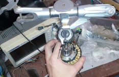
Above is a permanent magnet rotor, the magnets are embedded slightly deeper so they are a little farther away from the magnetic fields of the electromagnets, this allows them to run a little cooler. It is called "Interior permanent magnet /IPM, instead of the common "surface mount magnets"

View attachment 6

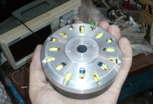
Switched Reluctance / SR rotor with Eight salient lobes. No magnets here, only laminated steel. It could be used in an 10/8 or 12/8 configuration.

MotorSR9.png

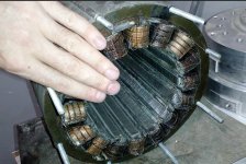
one phase of the 4-phase 8/6 SR motor

MotorSR17.png

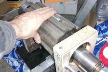
Synchronous Reluctance (SynR) rotor being installed into an industrial inductance stator

View attachment 3

The flux paths of a SynR rotor, no magnets, only laminated steel shown

MotorSR6.png

Thin steel laminations in reluctance motors

MotorSR2.png

a simple 3-phase 6/4 SR motor

MotorSR19.png

A simple 3-phase 6/4 SR motor
 
Thanks a lot spinningmagnets. That really helped me take it all home and understand it all. Thanks for taking the time and put in the effort to educate an old man. Much obliged.
 
The biggest difference between synchronous reluctance and switched is that sync ones typically have the phases all joined together like conventional 3 phase motors. Switched reluctance typically have completely separate phases that each have their own ground connection.
 
Back
Top