Eaton APR48-3G 1.8kW Light Compact Charger PSU

Yes sure you can.
Here is a similar solution:
http://electrotransport.ru/ussr/index.php?topic=28615.msg899947#msg899947


As voltage above 68V, Not sure that it is possible.
 
Allex said:
Yes sure you can.
Here is a similar solution:
http://electrotransport.ru/ussr/index.php?topic=28615.msg899947#msg899947


As voltage above 68V, Not sure that it is possible.

Thanks, I ordered the cable and am going to program the power supply when I receive it. I'll let you know how it works out. 3 of these would make the perfect charger for my hybrid car battery if I can program the current or power output.
 
Allex, after you removed those pop rivets to open up the power supply. What did you do to close up the case?

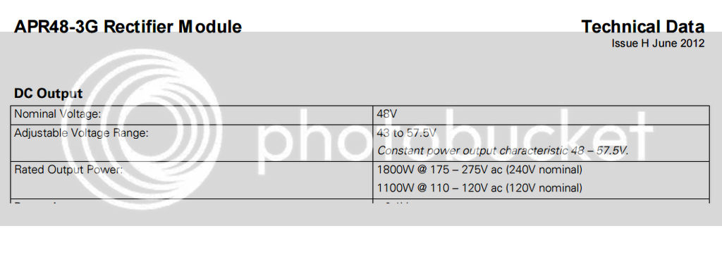
Just wanted to update that I believe based on the specs that if you use constant power, the voltage range is 48-58.

Because it says in the spec sheet "Constant power output characteristic 48 – 57.5V." and lists voltage range 43 to 57.5. I assume constant power is based on adjusting the amps?? Mean you can adjust say 43 volts and 5 amps, only 48 volts and 5 amps. Kind of sucks if you are between voltages when using more of these units.
 
Used pop rivets again, the tool does cost less than 10 bucks.

Not sure what you mean but one of my PSUs is running 43V10A and another is 44V10A
 
Allex said:
Used pop rivets again, the tool does cost less than 10 bucks.

Not sure what you mean but one of my PSUs is running 43V10A and another is 44V10A

Thanks, I didn't realize the tool was so cheap.

Just quoting this from the APR48-36 Technical Data sheet.Where is says the Constant power output.

 
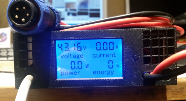
My Eaton encapsulation with meter:

170111024504443091.jpg


170111024608752346.jpg


The power meter is extract to: http://www.ebay.fr/itm/DC-100A-LCD-Volt-Current-KWh-Watt-Panel-Power-Meter-Ammeter-Voltmeter-Multimeter-/282018697753?hash=item41a99fd219:g:CAsAAOSw-itXvUsk
Box is printed with 3D printer (thank's Snickers for the design)

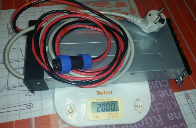
More info here: http://vae-tech.forumactif.org/t126-chargeur-1800w-40-60v-et-15-kg-origine-serveur
 
I like that amp and volt meter. That makes things really easy to make sure you are not going to overcharge the battery.

Question, The meter you linked is for AC electric and rated for 80-260 volts. How are you using it for DC and at 43 volts?
 
This worked for me, but try at your own risk.

Kahzama

Command---> Read Chip Signature (to see if wired correctly)
You might see this warning "Error Setting USBasp ISP Clock" when using Kahazama with a certain type of USPasp programmer, click ok as it does not affect the programming process.

I had a flashing yellow light when hooked to the computer and the lights would flicker when programming.

Command
Read Chip Signature (This is the check to see if the computer is communicating with the power supply)
1. Read EEPROM to buffer (Pulls .hex file from power supply)

File
Save EEPROM buffer as….
a. Save EEPROM in folder with srec_cat program. Srec_cat is a conversion program and will convert hex to bin and back again)

Srec_cat Conversion

Open CMD Prompt file directory which contains srec_cat program
To go to folder containing srec_cat in CMD prompt hold shift and right click on folder containing srec_cat “open command window here”

Type code in CMD prompt: "Srec_cat (Your file name).hex –intel –o (Your file name).bin –binary"
(This converts .hex to .bin and vice versa. -intel (type of hex) or -bin (binary)

Eaton Patch Tool

Once .hex file has been convert to .bin open Eaton Patch Tool and open .bin file. Change values to suit needs

Power supply range
Voltage: 43 - 57 volts
Amps: 0? - 37 amps

Once settings are ok click Patch – Save as …… ideally it would match your settings ie) 49v5a.bin
Save file in same folder as srec_cat program

Srec_cat Conversion

Convert .bin to .hex in cmdprompt so that Kahzama can read file.

Kahzama

File
Load EEPROM file to buffer. (Find file we just converted to hex.)

Command
Write EEPROM buffer to chip
 
If anyone here is interested in an Eaton APR48-3G let me know I have a spare new in the box. PM me.
 
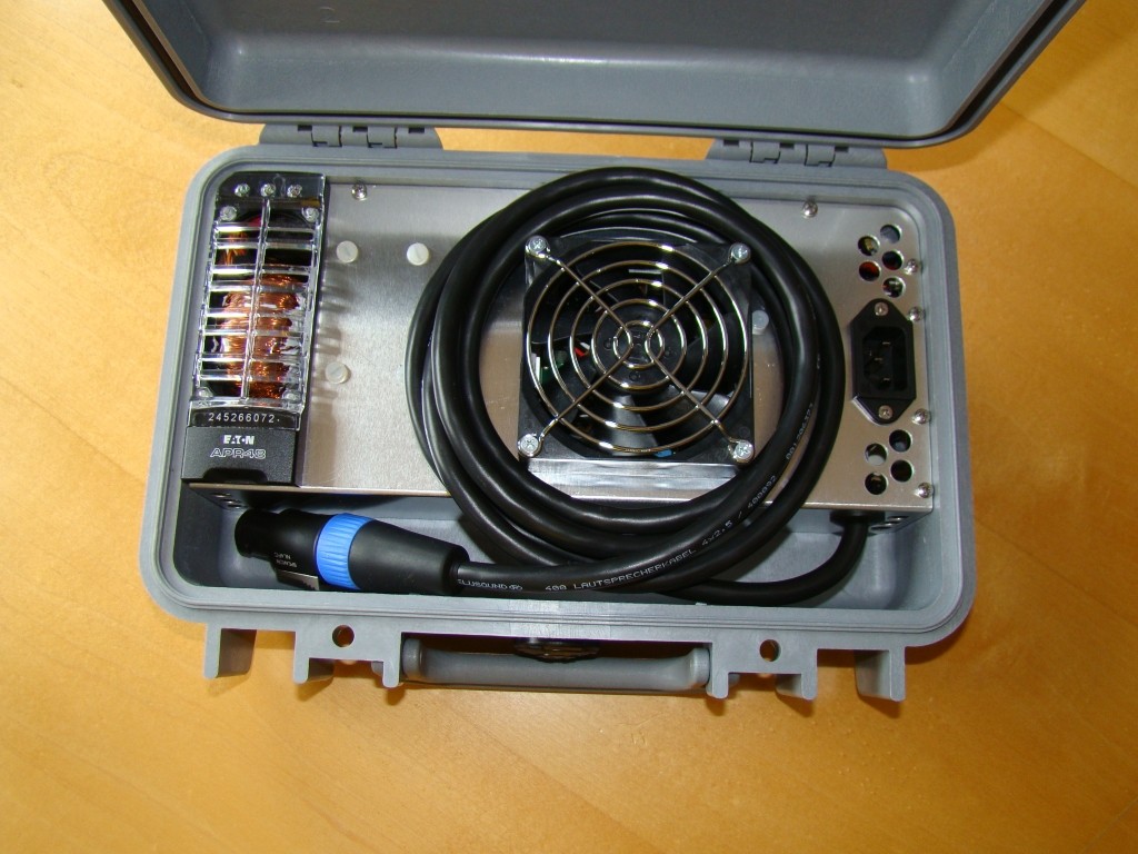
Does someone has a box or something like that to protect it a bit?
 
DasDouble said:
Does someone has a box or something like that to protect it a bit?

I have put my APR48-3G into a Peli Case as shown elarier in this thread. If you have the time, than check out my conversion thread.
Recently i got the newer APR48-ES 2000W on which i will do the same if time allows.

7sWyIm.jpg
 
madin88 said:
DasDouble said:
Does someone has a box or something like that to protect it a bit?

I have put my APR48-3G into a Peli Case as shown elarier in this thread. If you have the time, than check out my conversion thread.
Recently i got the newer APR48-ES 2000W on which i will do the same if time allows.

7sWyIm.jpg

Can you maybe tell me what specific case you used? Seems like there are a lot in forms and sizes..
 
Hi,

so the absolute lowest to programm teh Voltage is 43 Volts ?
how about current ist it 0-100% adjustable ?

and could you think of any simple solution how i could lower the Voltage to 41Volt beeing able to charge 10s until 41V?
greets

Notger
 
Im not sure if it will lower the current or the voltage, but you could put a resistor between it but thats not the most clean solution as you will waste a lot of energy.. :roll:
 
must be a quite big resistor 50-100Watts to be safe with charging high watts, but jest if i would stick to a certain Output Amp i could use such a Resistor.

anyone experiences with the hardware-mod, the resistor or potentiometer mod described in one of the first pages?
is it just a hardware possibility of the 43-57Volts, or does it change anything different ?

greets
Notger
 
Allex said:
Just do the software mod, it is on the first page.

But will the Software-Mod allow to go down to 41 or even 40,5 Volts ?

greets

Notger
 
Adjustable Voltage Range: 43 to 57.5V

You can always try to set a lower limit, if it does not accept it it will just run at the lowest possible.
So if you set it at 41 and this is a no go it will run at 43
 
Allex said:
Adjustable Voltage Range: 43 to 57.5V

You can always try to set a lower limit, if it does not accept it it will just run at the lowest possible.
So if you set it at 41 and this is a no go it will run at 43


Ok, so you did not try it, then its up to me, ill buy the USB Link and will see
 
I'm doing some tests with the APR-3G rectifier.

I have connected the charger with the default programming. with the change of voltage to 67.2V. to charge a 16S li-ion battery. I changed the 3 output capacitors to 63V for a smaller 160V.

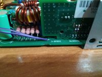
I changed the voltage by cutting the two tracks and adding a resistance. the photos are not the same as the first page. works the same. look at the photo. The cables connect to a resistor.

I plugged the charger into a plug meter. the network is 230Vac 50hz.

When plugging the charger into the battery the meter is marked 2570W.

I measured the battery voltage and it was at 62V. if the current limiter is 38.5A as it puts in the programming. the rectifier is giving 2400W output. much more than the nominal 1800w.

Have I left the rectifier withstand 2400W? Under the amps at 31A to lower the power to not burn it?

Can I use normal type capacitors? Do I need capacitors low resistance and high ripple current, like the original capacitors you have installed?
 

Attachments

  • IMG_20171003_032209.jpg
    IMG_20171003_032209.jpg
    132.7 KB · Views: 4,117
vicens said:
I measured the battery voltage and it was at 62V. if the current limiter is 38.5A as it puts in the programming. the rectifier is giving 2400W output. much more than the nominal 1800w.

so wait, you managed to get 62 Out of the PSU ?
but with a resistor Mod, not with the Software right ?
 
notger said:
vicens said:
I measured the battery voltage and it was at 62V. if the current limiter is 38.5A as it puts in the programming. the rectifier is giving 2400W output. much more than the nominal 1800w.

so wait, you managed to get 62 Out of the PSU ?
but with a resistor Mod, not with the Software right ?


with resistance mod. set to 67.2V in vacuum.

The maximum voltage with resistance mod is 70V.
 
vicens said:
notger said:
vicens said:
I measured the battery voltage and it was at 62V. if the current limiter is 38.5A as it puts in the programming. the rectifier is giving 2400W output. much more than the nominal 1800w.

so wait, you managed to get 62 Out of the PSU ?
but with a resistor Mod, not with the Software right ?


with resistance mod. set to 67.2V in vacuum.

The maximum voltage with resistance mod is 70V.

Yeah - that sounds great !!

Any idea or experience if you could also set it down to 41 Volts ? (10s)
I'm searchin for a "Multi-Charger" for 10s and 15s 41Volts and 61 Volts ?

and ist there actually a possible resistor Mod for adjusting the Amps too ?

greets and thanks

Gernot
 
notger said:
vicens said:
notger said:
vicens said:
I measured the battery voltage and it was at 62V. if the current limiter is 38.5A as it puts in the programming. the rectifier is giving 2400W output. much more than the nominal 1800w.

so wait, you managed to get 62 Out of the PSU ?
but with a resistor Mod, not with the Software right ?


with resistance mod. set to 67.2V in vacuum.

The maximum voltage with resistance mod is 70V.

Yeah - that sounds great !!

Any idea or experience if you could also set it down to 41 Volts ? (10s)
I'm searchin for a "Multi-Charger" for 10s and 15s 41Volts and 61 Volts ?

and ist there actually a possible resistor Mod for adjusting the Amps too ?

greets and thanks

Gernot


This rectifier can be programmed from 43 to 57.5V

Should be good to program from 11 to 13S.

The mod voltage of 14S can be made. without changing the capacitors.

The mod can be made from 15 to 16S. changing the capacitors.

From 10 to 15S there is much difference.

If you want to charge 100%. the 10S configuration. and the battery has bms. you can try the rectifier. It might work.
 
Back
Top