KT motor controllers -- Flexible OpenSource firmware for BMSBattery S/Kunteng KT motor controllers (0.25kW up to 5kW)

casainho said:
So, I own a S12S (S12P moded to S12S) and I it works very well with current firmware. The 72V version I don't know which changes are between the 48V and 72V versions, but I would say only the voltage resistor that reads the battery voltage (not counting with changes on capacitors, etc to handle the higher voltage). That difference I think you will be able to find using a multimeter.

I think someone will want to use the most powerful version of this controllers, and would be great to get knowledge on how to use them. I think Kunteng sells even an higher current version than BMSBattery sells. But go with BMSBattery if you can, because no BMSBattery versions may have some significant changes in hardware, mainly on the available cables/inputs to the microcontroller.
So if you're correct about the changes to the 72V version, adapting this firmware should be a no-brainer. Nice!

Your P-to-S mod and geofft's mention of the S09 has also piqued my interest. BMSB offers a S09PP 72V 1kW controller which comes in a smaller case, which would be perfect for me. So now I, too, wonder if that one can also be modded into a sine controller. Unlike the others, this one doesn't have an official sine version.
 
geofft said:
I also have been watching this thread with great interest and would like to add my congratulations to you guys on your efforts so far. Will definitely be trying your firmware sometime in the future, I'm no coder but can usually follow instructions to get these things loaded up and working.

Just a small question for casainho regarding the S12P to S12S mod you describe in the link. When this mod is done is the controller still run sensorless or do you add the three hall wires and run it sensored? I ask this as I have a S09P sensorless controller (ordered in error) that I would like to mod to S09S sinewave/sensored operation - is that possible? - unfortunately I have found that my Q128H does not run well in sensorless mode.
Hi Geoff.

Thanks for the feedback. Can you please share with us some information, so we can understand better your needs:
1. can you please tell us why are you interested to use the firmware?
2. what bicycle type do you have, what is the kind of usage?
3. which motor, battery pack voltage?
4. do you use throttle, PAS, torque sensor, regen brakes?

So I did the mistake to say it was an S12P while it was instead a Kunteng some version with mosfets but without the phase B current sensor/sinewave.
You can try to go ahead and try find if the circuit for the hall sensors is populated, like the resistors, capacitor... follow the schematic of the S06S!

You may have an Kunteng controller that have hall sensor cables but that does not do sinewave. I did mod this controller to a S12S version (sinewave control version). Seems the boards are equal but with one important missing component (and expensive one I think): phase B current sensor.
 
Thanks for the feedback. Can you please share with us some information, so we can understand better your needs:
1. can you please tell us why are you interested to use the firmware?
2. what bicycle type do you have, what is the kind of usage?
3. which motor, battery pack voltage?
4. do you use throttle, PAS, torque sensor, regen brakes?

Thanks for your speedy reply, answers to your enquiries below:-

1. I'm using the PSWpower version of the S06S (17A) - although this controller works well it has a couple of issues which I'm hoping your firmware may allow me to 'adjust'.

a) Very non-linear reaction to throttle changes with a huge step in motor output at one point. The voltage output from the thumb throttle itself is correctly linear.

b) I'm using an LCD3 display with 5 power levels - the 5 steps are not even, levels 1-2-3-4 give nice even increases, but 4-5 gives a much larger increase in power level, almost like a step has been missed between 4-5. I often find on hills I'm having to switch 4-5-4-5 etc to get the right assist level.

....I don't know if these issues are normal or maybe peculiar to my controller - I have a further S06S (20a) on the way to check this out and use for trying your your firmware.

2. I'm using a mountain bike which I have converted to be a more comfortable 'street cruiser'. I do some off-road riding but only on relatively smooth tracks.

3. Q128H rear geared hub motor, 12s lipo (44-50v).

4. I use just PAS and throttle. Regen is not possible with the Q128H geared motor, torque sensing is something I may play with in the future.

The S09P I have is the BMS battery version, without hall wires. I think I will go ahead and try the mods I mentioned, I've nothing to lose in doing so. This probably won't happen until the new year but I'll let you guys know how it goes.

Geoff.
 
geofft said:
1. a) Very non-linear reaction to throttle changes with a huge step in motor output at one point. The voltage output from the thumb throttle itself is correctly linear.
For me my throttles are no linear - how did you verified that the output voltage is correctly linear?

Example of ADC value for throttle (purple lines) -- in the middle is kind of flat and on the final it jumps very fast to max value:


geofft said:
4. I use just PAS and throttle. Regen is not possible with the Q128H geared motor, torque sensing is something I may play with in the future.
Why do you use throttle if you also have PAS?
 
Hi, my method of checking the thumb throttle was pretty unscientific - just connected a voltmeter to the signal wire from the thumb throttle, operated it gradually and checked the signal voltage rose in a similar manner. Which it did - the sudden step in motor output at around 1/3 throttle was not present on the signal output from the thumb throttle. I have also tried another throttle with the same result.

I have always used PAS and throttle in combination, even with PAS I find the handlebar throttle is very useful for pulling away quickly from a standstill, temporarily adding a bit more power when the selected assist level isn't quite enough or simply adjusting power when I can't be bothered to keep the switching assist level up and down. I don't think I'm unique in riding this way, I'm sure many people ride PAS and throttle in combination.

As I said, I'm not completely sure as yet that these issues are a factor of the controller firmware, it may be be a feature of my individual setup. I suppose I'm thinking that a more configurable controller (like you guys are working on) could get round these sort of issues, often just personal preferences.

It's probably also true that I'd like to try your developing firmware "because I can" as we say - just idle curiosity really.... :wink:

Anyway good luck with your efforts, it looks like you're making great progress.

Geoff.
 
rowbiker said:
The "Copenhagen Wheel" ebike (unified rear wheel hub) uses pedaling in reverse to 'turn on' regen braking. In my limited experience riding this configuration, it works very well.
Great to know :)
 
Thats normal with these controllers on stock firmware, whatever you set at P3 its not toque control, theres still relation with speed, so at 1/3 its full from standstill. I am using 18Fet at almost 4Kw and with this power its a big problem. Planning to buy another controller and try this firmware.

Guys please, anyone knows what has to be done to get CSD19536KCS mosfets working while there was irfb4110z original? If the drivers need to be modified? Like some smd capacitors and resistors..

If I get it working, than with this firmware we can safely get 24Fet kunteng pulling 180A at 72v (6fet 45A) with upgraded traces and wires for sure.
 
honya96 said:
Guys please, anyone knows what has to be done to get CSD19536KCS mosfets working while there was irfb4110z original? If the drivers need to be modified? Like some smd capacitors and resistors..

If I get it working, than with this firmware we can safely get 24Fet kunteng pulling 180A at 72v (6fet 45A) with upgraded traces and wires for sure.
Maybe is better for you start a new thread specific about that mod, to improve hardware of the controller. Maybe you will get attention from hardware guys...

I would so see that mod!! :) :) and also the ebike that will be driven by that monster controller :)
 
It will be my 60kg Vector frame bike with qs205 v3 50H motor and both moto tires. Get ready to remove the 72km/h speed limit :D would be great if it shows 1 again after reaching 99.
 
casainho said:
I use both signals to get the direction and count how many steps, see the image:
OK, that's a simple way of encoding a quadrature signal, already. So, a quadrature PAS or the Thun torquesensor or the Sempu third generation torquesensor, that are using quadrature signals, should work with this code.
But for the most common simple PAS we have to add another function in the fast loop, something like this

Code:
if (PAS_Pin = high) PAShigh_counter++;
else PASlow_counter++;

If (PAS_Pin=low && PAS_Pin_old = High){    //falling edge
If (PAShigh_counter>PASlow_counter) ... //you are pedaling forewards
If (PAShigh_counter<PASlow_counter)... // you are pedaling backwards

PASlow_counter=0;
PAShigh_counter=0;
}

regards
stancecoke
 
stancecoke said:
OK, that's a simple way of encoding a quadrature signal, already.
So for torque sensor I did:
1º calculate PAS cadence (1º piece of code)
2º did a hack: added a another PAS (PAS2) to the torque sensor (2º piece of code). With the PAS2 I as able to implement that regen ebrake like coast brakes

1º is mainly for torque sensor, maybe it can be common to general PAS, I need to see. And yes, I understand that on general PAS we can find the direction by looking at with of ON time VS OFF time.
One way or other, I may out put #ifdefs and user can choose on the Java tool.

2º I like the result but since it involves an hack, maybe not much users will make and use it, so may no be useful to be on the main firmware... I don't know.

I want to install a PAS on one of my ebikes to develop the PAS code. I hope to do it next week.
 
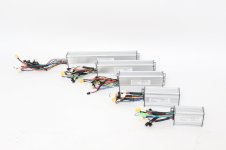
I found a good picture of all base kunteng controllers 6,9,12,18,24Fet. Its from Risunmotor.com they have best prices I found yet and duty free shipping, If you take whole kits, not just single controller.

Maybe you want to add this picture to the project page. :)
 

Attachments

  • risunmotor_controllers_1.jpg
    risunmotor_controllers_1.jpg
    84.9 KB · Views: 2,470
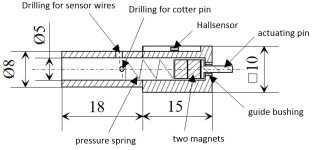
For having infinitely variable regen, I've modified a brake lever. With a linear hall sensor inside, it has an analogue output now. :D

[youtube]gE2KvwUhD1w[/youtube]

index.php

index.php

index.php


regards
stancecoke
 
Thank you for that information.
here two more pictures with some details:

index.php

file.php


regards
stancecoke
 

Attachments

  • linear break lever drawing.jpg
    linear break lever drawing.jpg
    56.7 KB · Views: 2,470
@casainho
Nice to see you involved in stm32f1 firmware development on eggelectricunicycle project :)
I like that kind of architecture...

Just few questions:
1) Can I obtain the raw 6 PWM signal from controller?
2) Can I disable hall sensor control and PAS but have a still working controller?

Sorry for my stupid questions...
 
dkmorb said:
@casainho
Nice to see you involved in stm32f1 firmware development on eggelectricunicycle project :)
I like that kind of architecture...

Just few questions:
1) Can I obtain the raw 6 PWM signal from controller?
2) Can I disable hall sensor control and PAS but have a still working controller?
Thanks. Maybe someday I will be back to electric unicycles :)

About your questions, I don't know if you are thinking in making your own controller. If so, you can buy the microcontroller from Ebay and a board here: https://www.waveshare.com/stm8s-discovery.htm

1. Yes, the raw 6 PWM signal are available -- see S06S schematic our the firmware source code file gpio.h

2. No and I don't know if you did understand already but the firmware needs a hall sensors, the motor must have hall sensors! No sensorless, not possible with this limited limited STM8 8 bits microcontroller. The SxxP controllers do sensorless but not sinewave, just 6 steps!!
You can read about it here: https://opensourceebikefirmware.bitbucket.io/Various--Endless-sphere.com_forum_messages--2017.08.23_-_SxxP_versus_SxxS_versus_LSW-675.html
Hmmm, hall sensor control?
PAS: yes, the firmware is structured as motor controller (motor.c) + ebike app (ebike_app.c). The PAS code is on ebike app (the main code) and we can do another application other than ebike and still use the motor controller. For instance, we can do a generic motor controller, that is commanded by UART commands from an Arduino...
 
Ok, I see, so no sensorless aproach by stm8 cpu...'cause we need to sample the zero crossing between interpolating phases, right?
Well, I order 2 little board with stm8 :oops:
And what about, in the future, porting the code to stm32fXXX and then implementing sensorless mode? :roll:
I need to put my hand in the code to understand!
 
dkmorb said:
Ok, I see, so no sensorless aproach by stm8 cpu...'cause we need to sample the zero crossing between interpolating phases, right?
Can't do that algorithm with sinewave/FOC.

dkmorb said:
And what about, in the future, porting the code to stm32fXXX and then implementing sensorless mode?
Do you need sensorless? Why sensorless?
Kunteng controllers go from 6 mosfets up to max of 24 mosfets. 24 mosfets --> 72V, 70 amps peak current, which is 5KW -- and they are cheap and widelly available controllers. The same knowledge and firmware we are building have all that potential, I don't think there are other controllers with this potential.
 
Alan B said:
If you make a little PC board to convert zero crossings to 5V (three comparators) and feed those in where the hall sensors usually go, and adjust the angle to compensate, it should work in six step mode. Not in sinewave mode, so turn that off.
That is what SxxP controllers does:

The S06P controller don't do sine wave motor control but just 6 steps. When compared to the S06S controller:
• don't have the phase current sensor (the place is on the board but is empty)
• have a secondary board that connects to the same pins as hall sensors:
◇ have a STM8S003F3P6 (with available header to be programmed)
◇ have an LM339
◇ I would say this board does BEMF signal output to simulate the hall sensors signal, just like on the KU63 controller circuit

39-2.png
 
Stancecoke,
I can use P3 for user choose a variantion of control mode.
Let's say I am implementing throotle:
P3 = 0: speed + current
P3 = 1: current

OR

P3 = 1: duty_cycle?

because with current only, motor will always run at max speed if wheel on the air...
 
Back
Top