bluetooth BMS?

\\ (•◡•) / said:
Wow, such an informative thread, i was actually looking at getting on of the 300Amp smart bms's for my lg hg2 20s10p pack about a month ago but went with this bms instead:

At the time I couldn't find any information on the smart bms so I went with this one instead, now I'm regretting that. Is it worth switching to the smart bms? I haven't even used this bms yet so it might be a bit sad to already retire it but with the extra features of the smart bms it's tempting. Also does the bms i purchased look particularly good anyway? I paid 200 aud for it shipped from alibaba, Would love some opinions, i defiantly don't mind spending the extra 160 aud for the new bms if it will help my packs lifespan. Thanks

This BMS uses TO-247 mosfets. There's loads of options in this package for insane amperage. OF course HY mosfets are Chinese and generally not as good as the legit parts that are similar specs.

I think your BMS uses the Mitsumi MM3474 LION battery controller chip. In the better dumb BMS, this is common. I have several dumb BMS with this IC and I like it a good a lot.

The smart BMS we've been talking about here is working out well so far...excepting the HY mosfets and the copper busses. Smart is definitely better than dumb. With a dumb BMS, you have to monitor cells yourself with something like a celllog or just trust the BMS is behaving. With a smart BMS, it tells you all that information and has settable options. A dumb BMS is pretty much plug it in and whatever it was designed to do is what it does. A smart BMS allows you to set lots of options for your specific desires and requirements.

I don't know anything about your BMS beyond the pictures you posted, but it doesn't look like it's garbage. I wouldn't be afraid to use it.
 
flippy said:
ElectricGod said:
Has anyone tried running these smart BMS from just the balance connections only? If you do and don't care about over current or LVC cut-off, then this BMS could make for a decent smart balancer. Since no current passes through the mosfets the power section would be totally irrelevant and multiple BMS could be ran in series. If you needed 48S, run 3 16S BMS in series. Set each BMS like you would for a 16S pack. Since each BMS "sees" only the cells it is connected to and therefore is operating relative to those cells only, it never exceeds it's operating limits. Isolate each BMS from the others so there's no way for voltage cross contamination to happen and it should be 100% OK. Each BMS won't read current and it won't read total pack voltage, but if all you care about is balancing and cell status, then this would work pretty well.

I'm not ready to do this test yet, but soon. I have 4 of the 16-20S smart BMS and 32S of LIPO at 16,000mah. I can use this to test out series connection. It shouldn't be a problem at all. you will connect to each BMS, check it's cell status, connect to the next BMS and repeat. My end goal is to see if I can get these BMS to operate at an LVC of 2 volts and HVC of 2.8 volts and then build an LTO pack with 48 cells. The spec sheet for the TI charge controller says it can't go this low, but a friend of mine sent me an email saying he had messed with LTO voltages on this BMS and got it going, but doesn't remember the details.
it only draws current from the last positive balance input. that is were i meaure all the current being used by the board.

is it possible to just dump the C- side entirely and just bypass the entire mosfet array on that side? it would bypass the shitty mosfets low voltage ones on that side and reduce rdson as a bonus.

Yes!!! You don't need C- at all. I don't use C- if I can avoid it. All my power in and out of the BMS goes through P-. If you look at my upgrade posts, you'll see that I only upgraded the mosfets on the P- side. I couldn't care less about the C- mosfets since they never see use.

On a related note...
I haven't done this, just thought about it so far, BUT, there's no reason why the C- buss can't be connected over to the batt- buss. Then disconnect the C- gate control and instead connect the P- gate control to the C- mosfets. All power in and out of the BMS still happens at P-. This effectively doubles the number of mosfets on the P- side since now the P- and C- mosfets are in parallel instead of series. This makes the BMS capable of double the current handling with no other changes. Any BMS can be modded in this fashion.
 
today i charged my new battery through the BMS and also did some test runs.
after charging with 15A for an hour and a half the battery was at around 4.1V/cell, but deltaV from lowest to highest cell was around 40mV. WAY TOO MUCH for brand new genuine samsung 30Q cells.
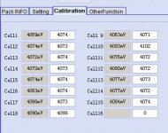
i did some voltage checks some weeks ago and found the bms' cell monitoring quite accurate, but i did a more in depth testing today and got this result:


d9bcc40e-fc6c-46bd-96b0-f113d27ea49d.jpeg


left column is bms' voltages and the right ones the ones i measured with my fluke dmm. so to me it seems you can't trust the bms' measurements and it's necessary to calibrate it. two cells show too high voltages, maybe because of false measurements and false balance actions of the bms.
all other cells are within 2mV. i let the bms balance now over night and we'll see the results tomorrow.
 
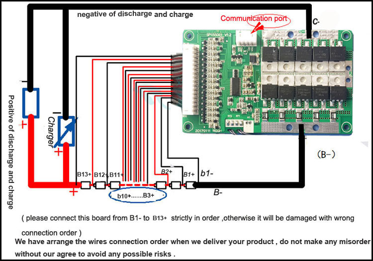
i also have a major issue with the bms now. i installed the switch and can turn the discharge fets on/off with it. but the bms shuts down when pulling some amps only. my CA just goes out and reboots. charger is connected to C-, battery to B- and controller to P-.
any idea why that could happen?
 
izeman said:
i also have a major issue with the bms now. i installed the switch and can turn the discharge fets on/off with it. but the bms shuts down when pulling some amps only. my CA just goes out and reboots. charger is connected to C-, battery to B- and controller to P-.
any idea why that could happen?

Probably the JST connector or maybe current is set too low.
 
izeman said:
left column is bms' voltages and the right ones the ones i measured with my fluke dmm. so to me it seems you can't trust the bms' measurements and it's necessary to calibrate it. two cells show too high voltages, maybe because of false measurements and false balance actions of the bms.
all other cells are within 2mV. i let the bms balance now over night and we'll see the results tomorrow.

Another reason could be temperature drift.
Lets say one cell has higher voltage and the BMS starts to enable balancing on this input.
Now the resistor gets hot and heats up the BMS board. Due to the temperature rise the accuracy of the voltage measurement could become worse.

I once worked with BMS which showed this behaviour and when asking the dealer, he said this is because of the temp drift. The BMS wen't back.
 
Could be but sounds unlikely to me. Those little resistors don't really get hot. And this happened immediately after I connected everything together. So the pcb was cold. And even if the voltage measurement was completely messed up it would not have passed low or high voltage cut off.
 
it seems to me that the BMS is toast. i can still charge, it balances, but it won't turn on the output stage anymore. and it can't sense the current that way.
i will turn on the output stage somehow though when i connect the charger. but i will cut power under little load.
something strange is going on. maybe i destroyed something when i connected charger and controller to different ports?!?! the manual clearly states that both needs to connected to C-. how unlogical this may sound.

EDIT: i guess i found the problem. i installed new jst-xh 2pin connectors for the temp probe and the switch. when i installed top and bottom plate those connectors were higher than the original ones and when i screwed the two parts together it bent the pcb. this may have destroyed some traces. when i bent the pcb and put some pressure on it it works again. i may try to reflow it and see if this fixes it, but i guess not. so i'll order a new one.
 
izeman said:
the manual clearly states that both needs to connected to C-. how unlogical this may sound.

If you connect the load also on the "C-", the BMS is able to cut off if you overcharge your pack during regen (this has something todo with the diodes in the FET's).
But doing so means you have twice the resistance or resulting heat during discharge as the current is flowing through all FET's, while if attached to "P-" the current is flowing only through one bank of FET's.
This is where the confusion may come from. Some pics show charge and discharge are same and some show the separat connection.

edit: i would connect both to C- like this:

HTB1NfmBSXXXXXXOXXXXq6xXFXXXi.jpg


https://de.aliexpress.com/item/48V-...32733414980.html?spm=a2g0s.9042311.0.0.ecaGOR

thats the BMS i have bought for a 13s battery.
It makes no sense to have same number of FET's for charge and discharge if not connected like this. Otherwise, probably one single FET would have been enough for charging.
And guys, as you see the current flow is optimal and no need to solder copper bars to P-.
 
i ordered the 30A version of the BMS as it's $10 cheaper ;) i got enough FETs on the other BMS to swap them and make the new one a 60A version as well.
i will also swap the bleeding resistors of the old BMS and see if i can raise balancing current w/o any side effects on the BMS itself. i may add some maybe 0,5W 22Ohm resistors to tripple the current:

U = I * R = 0,045A * 75 Ohm = 3,4 V
P = U * I = 3,4V * 0,045A = 150mW

so a 22Ohm resistor would give around 3* 0,045mA = ~ 130mA and produce ~500mW

what do you think?
 
I think the 50mA balancing current is good enough for a properly build battery like yours, but if you like to swap the resistors than make sure to stay below the max power dissipation.

If i put 4,2V into the formula i get 35,3Ohm (for 0,5W). P= U²/R
 
madin88 said:
I think the 50mA balancing current is good enough for a properly build battery like yours, but if you like to swap the resistors than make sure to stay below the max power dissipation.

If i put 4,2V into the formula i get 35,3Ohm (for 0,5W). P= U²/R
Were you asking a question here?
 
madin88 said:
by madin88 » Sun Mar 11, 2018 10:55 pm

izeman wrote: ↑Sun Mar 11, 2018 12:35 am
the manual clearly states that both needs to connected to C-. how unlogical this may sound.
If you connect the load also on the "C-", the BMS is able to cut off if you overcharge your pack during regen (this has something todo with the diodes in the FET's).
But doing so means you have twice the resistance or resulting heat during discharge as the current is flowing through all FET's, while if attached to "P-" the current is flowing only through one bank of FET's.
This is where the confusion may come from. Some pics show charge and discharge are same and some show the separat connection.

edit: i would connect both to C- like this:

Hi thanks for your info, so in your opinion is it optional where we connect the Charge and disharge Minus to P- or C-?

or should we only connect Both charge and discharge NEGATIVE to the C- ? what are the pro's and cons vs the two options , Charge Minus to C- and Discharge minus to P- ?
 
Alex07 said:
Hi thanks for your info, so in your opinion is it optional where we connect the Charge and disharge Minus to P- or C-?

For this type of BMS, or any other BMS where charge and discharge can be the same -> YES.
But never connect the Charger to "P-", because the BMS cannot cut it off if there is something wrong.
Always connect it to "C-"!

or should we only connect Both charge and discharge NEGATIVE to the C- ? what are the pro's and cons vs the two options , Charge Minus to C- and Discharge minus to P- ?

If you connect the controller to "P-", the BMS cannot cut off if your pack gets overcharged by using regen (think of a fully charged battery and you riding downhill using regen all the time) . Thats the downside.
The positive thing about connecting the controller to "P-" is you can draw a bit more amps, as the current is flowing only through one bank of FET's (therefore only half the resistance).

If one manufacturer specifies a BMS for 30A, and the manual says "charge and discharge are the same", than it should work properly if wired up like this.
 
If you connect the controller to "P-", the BMS cannot cut off if your pack gets overcharged by using regen (think of a fully charged battery and you riding downhill using regen all the time) . Thats the downside.
The positive thing about connecting the controller to "P-" is you can draw a bit more amps, as the current is flowing only through one bank of FET's (therefore only half the resistance).

so when using this on a mid drive with no REGEN then we should just connect Controller to P- and charger to C-. i.e this risk does not exist and we just wire as per standard.
 
madin88 said:
Alex07 said:
Hi thanks for your info, so in your opinion is it optional where we connect the Charge and disharge Minus to P- or C-?

For this type of BMS, or any other BMS where charge and discharge can be the same -> YES.
But never connect the Charger to "P-", because the BMS cannot cut it off if there is something wrong.
Always connect it to "C-"!

or should we only connect Both charge and discharge NEGATIVE to the C- ? what are the pro's and cons vs the two options , Charge Minus to C- and Discharge minus to P- ?

If you connect the controller to "P-", the BMS cannot cut off if your pack gets overcharged by using regen (think of a fully charged battery and you riding downhill using regen all the time) . Thats the downside.
The positive thing about connecting the controller to "P-" is you can draw a bit more amps, as the current is flowing only through one bank of FET's (therefore only half the resistance).

If one manufacturer specifies a BMS for 30A, and the manual says "charge and discharge are the same", than it should work properly if wired up like this.

What you are saying is connect your charger to C- and connect the BMS output to the EV to P-. For charging only, if you bypass C-, the BMS can't turn off if there is an issue. Power to the EV is always controlled by the P- mosfets. I rarely use C- and it has never been an issue. I charge at P- and my chargers are set to whatever is the pack's fully charged voltage. Admittedly. IF a cell is badly out of balance, this might create an issue, but I have yet to see it happen. As the cells reach closer and closer to fully charged (charger output voltage), they take on less and less current until finally it is just a bare trickle. At this point, whatever low cells may still exist are the only ones taking current.
 
ElectricGod said:
I rarely use C- and it has never been an issue. I charge at P- and my chargers are set to whatever is the pack's fully charged voltage. Admittedly. IF a cell is badly out of balance, this might create an issue, but I have yet to see it happen. As the cells reach closer and closer to fully charged (charger output voltage), they take on less and less current until finally it is just a bare trickle. At this point, whatever low cells may still exist are the only ones taking current.

If you charge via "P-", in the worst case your battery could turn into flames. The BMS will try to balance overcharged groups, but it cannot disconnect the charger.
Yes you have right that something very strange must go ahead with a battery to make this happen. But why taking the risk? :)

On the otherside, a group that would become slighlty overcharged to lets say 4,3V could occur much more often, and such group would suffer damage.
If charing via "C-", the BMS would cut off the charger, bleed this group down, and enables the charger again. repeating until the pack is balanced.
 
C- is most important and all I use.
By C- going thru P- redundant protection. If C- is shorted, P- will turn of charger.
This has happened to me.
 
Inwo said:
C- is most important and all I use.
By C- going thru P- redundant protection. If C- is shorted, P- will turn of charger.
This has happened to me.

From what i know, there is a diode inside (any?) Mosfet between Drain and Source which means that current can flow always in one direction.
Thats the reason why P- is connect to Drain of it's belonging FET's, and C- is reverse connected to Source on the second group of FET's.
 
Don't know how it works. On several occasions, I've had shorted C- mosfets and could not charge. :?:
 
madin88 said:
Thats the reason why P- is connect to Drain of it's belonging FET's, and C- is reverse connected to Source on the second group of FET's.
afaik a FET doesn't care about the direction the current goes. that's why you can use regen on your controller. the output FETs become input FETs during regen.
 
izeman said:
madin88 said:
Thats the reason why P- is connect to Drain of it's belonging FET's, and C- is reverse connected to Source on the second group of FET's.
afaik a FET doesn't care about the direction the current goes. that's why you can use regen on your controller. the output FETs become input FETs during regen.

Yes correct...mosfets are not a diode junction like bipolars are. Current can flow in the mosfet junction in either direction.

Only enhanced mode mosfets have a back diode. Mosfets without diodes are readily available, but for uses on inductive loads, that diode is important. For a BMS, it could be either type of mosfet used, but with enhanced mode mosfets being soooo common and cheap, they commonly get used in BMS's. As a result the orientation of the mosfet is important so that the back diode does not effect shutting off current flow. IE: C- mosfets have their diodes reverse biased when charging from C-. From P-, current flow into the BMS if the mosfets are off is always possible since the back diodes are forward biased. However current flow out of the BMS if the mosfets are off is stopped since the back diodes are reverse biased. Effectively what this means is from P- you can't stop charging current only discharging current flow.

On the subject of over charging cells, I have yet to see this happen if I'm using a BMS. My chargers are always set to the pack full voltage. Let's say I have a 20S LIPO pack, fully charged at 4.1 volts per cell...since I use LION BMS's. That's 82 volts at 20S. With my charger set to 82 volts, and the pack nearing 82 volts, current draw from the charger drops off to nearly zero. At this point, it's only the low cells that are still taking current. All the fully charged cells are basically maintaining balance and that's all. I've checked this action many times and I just don't see cells getting beyond their balance voltage or 4.1 volts by more than .025 volts at most. The concern about using C- or not IMHO is completely unfounded.

I bet I could go to one of my EV's right now and run it down to my controllers LVC cutoff voltage which if I remember correctly is something like 3.1 volts per cell. I haven't watched charging action in many months so this is a good test and proof of what I have observed the last time I checked. I could connect up the correct charger and then charge the EV. I could check the cells one by one with my DMM and confirm what I just said. It is possible that some cells will charge to full sooner than others. BUT!!! As the entire pack gets close to fully charged total current draw from the charger drops off rapidly since the voltage difference between the charger and pack is so small. At this point, the high cells stay at their 4.1 volts (balance voltage thanks to the BMS balancing) and the low cells continue taking current. The over all effect at the charger is maybe .5 amps or less current draw spread across all the cells in the pack. This is well within the abilities of most balancing circuits to deal with at 16-20S. Watching the cells, I see the low cells still taking current (cell voltage continues to rise in the low cells) while the full cells are essentially maintaining balance voltage. The charged cells will rise to 4.125 volts and then drop back down when the balance circuit kicks in to bring them back down. This is typical BMS and RC charger behavior. They slightly over charge the cells on either side of a low cell and then discharge them. This action repeats until the low cell is up to full voltage. This is the action that I observe when I've checked charging and bringing up a low cell.

To get a result where high cells are over voltage would require that a cell was nearly dead flat. Lets assume a 20S pack charged to 82 volts with a cell at 2 volts. That means 2.1 volts is spread among 19 other cells or .11 volts over. With LIPO, where fully charged is 4.2 volts, this doesn't even constitute a concern at 4.21 volts per cell. With LION, it's more of a problem, but a battery fire is highly unlikely. If the BMS is working correctly, it would have long since reacted to this situation during pack discharge. When that one low cell dropped below the low voltage threshold it would have shut off the P- mosfets. IE: It would NOT have gotten to 2 volts before the BMS reacted. I've had this happen. I had a 20S, 20,000mah pack made of 10,000mah 4S multistar packs. A single cell was defective in one of the 4S packs. It had maybe 5000mah of capacity. AS a result that cell dropped below minimum voltage much faster than the rest of the cells in the pack. The BMS turned off the P- mosfets. I got home, opened up the EV to see what happened and checked all the cells and discovered that they were all at 3.8 or 3.9 volts except one which was at 3.2 volts. I then charged the entire pack and watched all the cells. The low cell increased in voltage, but of course when all the other cells were back to 4.1 volts, it was still at something like 3.8 volts. Current draw at the charger at this point was quite low...less than .2 amps. I periodically checked cell voltages and no cell got above 4.125 volts. The low cell eventually rose to 4.1 volts several hours later. After that I kept an eye on this weak cell and eventually pulled apart the pack after another 10 or so charges. My over all range thanks to the weak cell was reduced by about 30% when the BMS would cut out. Who knows why that cell had randomly died prematurely. I was never concerned about plugging in and walking away.

So then, lets talk about drastically BAD cell voltages for a minute. I'm sure NOT perfect and sometimes I do stupid stuff and kick myself really hard for it. This was at 12S and 48 volts. I was a noob to EV's. I had built 4 12S LIPO packs and was using a crappy charger that topped out at 52 volts. That's 2 volts over 4.2 per cell or 50.4 volts. This was not ideal for my LIPO packs and I had to watch that the voltage at the EV never went above 50.4 volts...or at least not by much. Charging over night was out of the question as all of the current from the charger would get spent in lots of balance circuits among 4 BMS in parallel and I'd possibly over charge my 4 12S packs. Fortunately the charger was capable of 2 amps so this wasn't a huge concern if I was watching the charge process periodically. I had purchased 3 BMS and they were in active use, but my 4th pack was waiting for it's BMS to arrive. It was common that I would plug in the charger into the EV and a couple of cell monitors into the unprotected pack. When the loud beeping started, it was time to pull the unprotected pack and finish charging via my RC charger. For whatever dumb reason, I flat forgot to do this. As you can imagine, that 12S pack was sitting at 52 volts or 4.33 volts per cell when I realized my mistake. I was thinking to myself why wasn't I hearing the cell monitors? I immediately realized it was becasue I had never plugged them in. I ran to the scooter and sure enough, every cell in that pack was at 4.3 volts and the pack was quite hot. I pulled it from the scooter, left it in the middle of the floor in my garage and let it cool down. All the cells now showed 4.4 volts!!! I then attached a load and pulled them back down to 4.1 volts per cell. That pack did suffer some loss of capacity, but no cell exploded or even puffed up. 2 weeks later it had it's own BMS. The other 3 12S packs that had BMS's were just fine. The cells despite the charger producing too much voltage were all sitting at 4.2 volts and soon were back down to 4.1 volts thanks to the LION BMS's.

A friend of mine was running with no BMS on 2 12,000mah 6S Multistar packs. I told him he really ought to invest in a 12S BMS, but he was cheap. One day, he forgot to charge and of course his EV didn't have a watt meter so he had no clue how low his LIPO packs were getting. He was close to home and the scooter felt super laggy, but he road home anyway. When he got home the LIPO packs were pretty hot...145F. He checked the voltages on them and one cell was at 0v and several others were at 1-2 volts. I think the highest cell was 2.6 volts. He asked me about what to do since it was pretty obvious that he had damaged his 2 LIPO packs. I told him how to recover low LIPO cells, but he was afraid of a battery fire. I got the 2 packs from him and proceeded to charge them. It's pretty easy to bring a low cell back to minimum voltage so that it can be charged normally. I've done it at least 50 times with 18650 cells scavenged from laptop packs. Now I was doing it for his really abused LIPO packs. All cells including the dead flat one came back up to full charge. It was badly bloated and when I tested it, had lost 80% of it's capacity. I pulled the cell and now had a 6S and 5S pack for free. I told my friend that I had recovered his packs, but he was afraid of them and let me keep them. They've seen use many times since then with no issues.
 
Back
Top