Votol EM-100 & EM-150 controllers

ah RTFM may help:
http://www.siaecosys.com/upfile/201909/2019090263764705.pdf
"Speed specification, can be adjusted according to customer tire model before shipment"

perhaps that's the reason why they quote this precise tire-ratio figures in their ads?

... just another question for carries list ....
 
wjr said:
ah RTFM may help:
http://www.siaecosys.com/upfile/201909/2019090263764705.pdf
"Speed specification, can be adjusted according to customer tire model before shipment"

perhaps that's the reason why they quote this precise tire-ratio figures in their ads?

... just another question for carries list ....

Then i´m pretty sure you can change that yourself in the software
 
Which software do you refer to?
The votol setup software? Natural choice, of course.
However, I can't find a speedo calibration value in the votol controller manual - just tickmarks to switch speedo output between "One-Lin" aka "Single line" and "Hall".

There is no setup software shipped with the speedo.
I don't want to reengineer the spedo controller software.
 
Hi guys, I just received my votol em-100sp(i think sp) and qs 2000w mid drive motor combo, This is my first e bike projects so I am sorry for the noob questions I am scared to let the magic smoke from my controller and motor!

At first I was planning on running 20s with this controller, but now am considering 18s instead, will this voltage be a problem? or do i need the adjust the voltage parameters in the controller config?
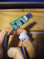
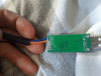
I have received a usb cable with my controller but it appears to only have two wires (orange and blue) the black wire has been cut from the plug, is this normal? or do i need to resolder a black wire to the gnd on the usb board? pic included hopefully.

1314.png

I am also curious as to how people mount this controller, is it safe to "hard mount" it to the chassis of my motorbike? (has full suspension) or am I better off soft mounting the controller with rubber stand off mounts?

I see on previous posts the grey/purple wire must be connected to battery positive voltage to operate, But am also curious as to if the boost yellow/white wire also needs to be grounded to access the full operating power? Is it safe to just leave this wire permanently grounded?

Are none of the "anti-theft" plugs/pins required for operation?

Again sorry for all the questions I am nervous and don't want to make a mistake so any help would be massively appreciated.

thanks!!
 
thanks for all those newbie questions I did not dare to ask :thumb:

regarding the 2-wire: might it be that it is CAN-based, not serial?
I'd expect 3 wires (CAN-Hi, CAN-Lo, GND) for CAN as well, bus as some dark remembrance I think I had read somwhere that GND is not mandatory (no warranty on that), or that only one CAN-wire might suffice for reduced levels of reliability.

Have you received pointers to the up to date manuals?
I have, but I'll ask them first wether it is OK to publish them here.
 
wjr said:
thanks for all those newbie questions I did not dare to ask :thumb:

regarding the 2-wire: might it be that it is CAN-based, not serial?
I'd expect 3 wires (CAN-Hi, CAN-Lo, GND) for CAN as well, bus as some dark remembrance I think I had read somwhere that GND is not mandatory (no warranty on that), or that only one CAN-wire might suffice for reduced levels of reliability.

Have you received pointers to the up to date manuals?
I have, but I'll ask them first wether it is OK to publish them here.


Yes I think you are right is it CAN based, upon closer inspection it seems my wires and mis-matched at the plug also?

On the usb the orange wire is connected to CANH and the blue wire is connected to CANL which appears correct to the wiring/plug diagram but when the use is plugged to the controller wiring harness the wires don't match up?
 

Attachments

  • IMG_20191113_133131865.png
    IMG_20191113_133131865.png
    45 KB · Views: 2,906
This is what I found:
pin 14 main plug - orange CAN-L/TXD
pin 15 main plug - blue CAN-H/RXD

have you asked QS for documentation?
I have, they sent me pointers, but haven't yet confirmed that I may publish them.
But I think you'll find earlier versions along this thread and I don't think that wiring changed.
 
wjr said:
This is what I found:
pin 14 main plug - orange CAN-L/TXD
pin 15 main plug - blue CAN-H/RXD

have you asked QS for documentation?
I have, they sent me pointers, but haven't yet confirmed that I may publish them.
But I think you'll find earlier versions along this thread and I don't think that wiring changed.

I am still waiting on a response from them..

I have been using the pinout diagram from page 1 on this thread but it says

pin 14 is CANH / txd orange
pin 15 is CANL / rxd blue

This matches my controller side plug

but the usb side orange and blue seems to be crossed over?
 
Hi this is dileep

I'm working on em-50 controller .
Is any body have data (software or program or communication protocol 485A & 485B etc...) about this controller please suggest to me.

Thank you
 
This is the link i got from Carrie.


Software and instructions for all the controllers.
http://www.siaecosys.com/list/?classid=102
 
ZERONEST said:
but the usb side orange and blue seems to be crossed over?

May they have switched it over between versions?
This would be weird :bolt: :flame: :cry:

ZERONEST said:
I am still waiting on a response from them..

Looks like a small team there, they have been at EICMA fair in milano last week, and 11.11 appears to be a holiday in CN....

Got response, may share pointers to manuals:

motor docs
http://www.siaecosys.com/list/?classid=96

Controller Docs:
http://www.siaecosys.com/list/?classid=102

including "Votol EM100SP EM150SP Wire Diagram" where on pg 2 I found the CAN pinout I mentioned
http://www.siaecosys.com/upfile/201909/2019090258058157.pdf

Speedo docs:
http://www.siaecosys.com/list/?classid=104

I think some of them may be more current than what you can find on the thread here.
I'd recommend double checking anyway, which may not always be easy.
Documentation standards have .... mhhhh,let's say .... still a little potential for improvement :wink:
But others obviously have managed to get their motors running - so there is hope, I hope :)
 
wjr said:
"Speed specification, can be adjusted according to customer tire model before shipment"
got this information confirmed by QS upon request.

I think I will simply mount a bicycle speedo to the front wheel :|
 
wjr said:
wjr said:
"Speed specification, can be adjusted according to customer tire model before shipment"
got this information confirmed by QS upon request.

I think I will simply mount a bicycle speedo to the front wheel :|

So it's not something you can change in the controller software ?
 
SilverLine said:
wjr said:
wjr said:
"Speed specification, can be adjusted according to customer tire model before shipment"
got this information confirmed by QS upon request.

I think I will simply mount a bicycle speedo to the front wheel :|

So it's not something you can change in the controller software ?
obviously, no.
I can't test live yet, because I first have to finish my battery pack.
No easy alternative 72V-source at hand :lowbatt:
 
wjr said:
SilverLine said:
wjr said:
wjr said:
"Speed specification, can be adjusted according to customer tire model before shipment"
got this information confirmed by QS upon request.

I think I will simply mount a bicycle speedo to the front wheel :|

So it's not something you can change in the controller software ?
obviously, no.
I can't test live yet, because I first have to finish my battery pack.
No easy alternative 72V-source at hand :lowbatt:

Many displays like this here, has a adjustable potentiometer on the black, to tweake the speed with.
https://s.click.aliexpress.com/e/n5GfQ3vA
 
Hello Everyone,

We are a motor sharing company and we are using the electric vehicles that have VOTOL em 50 Controller. We will be connecting our IOT device to this. We just got the wiring diagram and software, but we need more basic details like commands they use to start, stop, lock anti-theft etc. which is actually technical specification document.
we have tried to reach everyone but no luck, can someone here help us with this, please.

Thanks in advance for the help. :)
 
ZERONEST said:
wjr said:
This is what I found:
pin 14 main plug - orange CAN-L/TXD
pin 15 main plug - blue CAN-H/RXD

have you asked QS for documentation?
I have, they sent me pointers, but haven't yet confirmed that I may publish them.
But I think you'll find earlier versions along this thread and I don't think that wiring changed.

I am still waiting on a response from them..

I have been using the pinout diagram from page 1 on this thread but it says

pin 14 is CANH / txd orange
pin 15 is CANL / rxd blue

This matches my controller side plug

but the usb side orange and blue seems to be crossed over?

Just received mine.
My usb cable is exactly the same. Blue and orange is crossed in the plug, and the black Wire is cut.
 
SilverLine said:
Just received mine.
My usb cable is exactly the same. Blue and orange is crossed in the plug, and the black Wire is cut.


Ah ok, not sure what the reason for them switching them is, but it guess it doesn't matter, the colours are wrong but the connections remain the same, it made me believe they had made a mistake though..
 
Hi all, currently I'm working on next conversion and want to have working Magura throttle with Votol EM-150.
Does anyone have experience with this?
Tha case is that there is no config for throttle in Votol's software, and magura works from 0 to 5v.
So basically you have nothing at start, then full gas in the middle, and controller fault at the end.

I'm thinking about resistors at + and - cables to throttle, but maybe there is some hidden configuration in controller?
 
SilentEnduro said:
Hi all, currently I'm working on next conversion and want to have working Magura throttle with Votol EM-150.
Does anyone have experience with this?
Tha case is that there is no config for throttle in Votol's software, and magura works from 0 to 5v.
So basically you have nothing at start, then full gas in the middle, and controller fault at the end.

I'm thinking about resistors at + and - cables to throttle, but maybe there is some hidden configuration in controller?

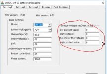
Here it looks like you can set the minimum and maximum voltage from the throttle/potentiometer?
 

Attachments

  • Capture.JPG
    Capture.JPG
    43.9 KB · Views: 2,783
Btw. I know the under voltage is 60v. But if i just want to connect to the computer without any motor, just to look at the settings in the software. Do i then still need 60v ?
 
Back
Top