New Crystalyte Motor series (HT35 / HS35 and HT24 / HS24)

Spacey said:
Edit due to me moaning on lol...

So 55V looks like it's going to cut off way too early on a 18cell Lipo pack which is a shame. They did send me the controller by mistake instead of the motor so I shall have to send it back to them, silly me though I expected it to have a CA connector.....doh!

Spacey said:
I mean there is no CA Cycle Analyst connector on the Sensorless Controller 40amp 72V, was hoping there was so I could maybe use it with my CA and lower the LVC cut off.

A CA will only allow you to raise LVC, never lower it. To lower LVC you need to either reprogram the controller or change R12 (or equv).

18S calls for a 54V LVC (assuming you want 3.0V per cell)
55V LVC = 3.05V per cell which is equivalent

55V is perfect for 18S. Why would you think that is too high? I actually set my LVC at least a few volts higher than the pack LVC. If you actually HIT pack LVC that positively means that at least some of your cells are way below LVC (due to the inevitable pack imbalance). So unless I have read wrong these controllers you guys picked up are fine for LVC.

As far as needing a stand alone CA... any controller can have a CA tap added fairly easily if you know how to solder. It is well documented here on the forum and in the CA documentation.

-methods
 
Yep, I actually run my 18S packs with a LVC of 58v
Or 60v with a 2v tolerance.
Even that is being a bit blase with no cell level monitoring. As methods said by the time the overall pack voltage hits the equivalent of 3v/cell you can bet half of them are ~3.3v and the rest at 2.7. Worse still if they're all ~3.4v and one has dropped to 2v. You'll pretty much kill that cell before the pack level LVC trips.
 
On the CA i can see the V of the packs and anyway and from my experience I have never needed to discharge them below 3.3v anyway. I am just trying to charge as often as possible.
Gary has been working on some BMS solutions for a while, but unfortunately I have not been lucky enough to get a response from him... :?:
http://www.tppacks.com/products.asp?cat=26

Hyena said:
Yep, I actually run my 18S packs with a LVC of 58v
Or 60v with a 2v tolerance.
Even that is being a bit blase with no cell level monitoring. As methods said by the time the overall pack voltage hits the equivalent of 3v/cell you can bet half of them are ~3.3v and the rest at 2.7. Worse still if they're all ~3.4v and one has dropped to 2v. You'll pretty much kill that cell before the pack level LVC trips.
 
Nice one guys, I'm still new to Lipo and thought that the voltage loss curve goes gradually down unlike the lifepo4 curve that goes down then holds for 80% of the charge before it drops off a cliff at the end.

Was worried that I would only have 2/3rds of my pack available before LVC cutoff.

I shall keep the controller then :) and try to wire up my CA to the controller, I only need it as a fuel gauge and speedo anyway.

Once again, thank you for the information.
 
you need to check the curve of the lipo cells. Each brand has a different discharge curve - for instance polyquest LP cells are pretty much flat all way down hence not really cool for ebikes. Anyway their prices are really high...

I actually have not seen any curves for turnigy / zippy but i think they are unlike polyquest. Im sure they are somewhere on the ES...
 
Spacey said:
Nice one guys, I'm still new to Lipo and thought that the voltage loss curve goes gradually down unlike the lifepo4 curve that goes down then holds for 80% of the charge before it drops off a cliff at the end.

Was worried that I would only have 2/3rds of my pack available before LVC cutoff.

I shall keep the controller then :) and try to wire up my CA to the controller, I only need it as a fuel gauge and speedo anyway.

Once again, thank you for the information.
Do not worry about 55v lvc for your 16s pack.
i used those 5.8ah8s packs on my bike all the previous summer and usually set lvc on CA even at 58volts! and was able to use 10.9ah out of 11.6nominal without problem even charging to only 4.16 per cell
so 55v in your case should be ok.
 
Pack level LVC is only for emergencies, wives, and drunken Australians!

If you are hitting LVC then you are either riding too far or your pack is not large enough. Please - never plan on riding to LVC.... On the rare occasion that I do, my LVC is set well above 3.0V/cell so I know that cells are not sitting empty for the hour pedal home :| And even then, I kick my self in the ass all the way back.

-methoods
 
wojtek said:
you need to check the curve of the lipo cells. Each brand has a different discharge curve - for instance polyquest LP cells are pretty much flat all way down hence not really cool for ebikes. Anyway their prices are really high...

I actually have not seen any curves for turnigy / zippy but i think they are unlike polyquest. Im sure they are somewhere on the ES...

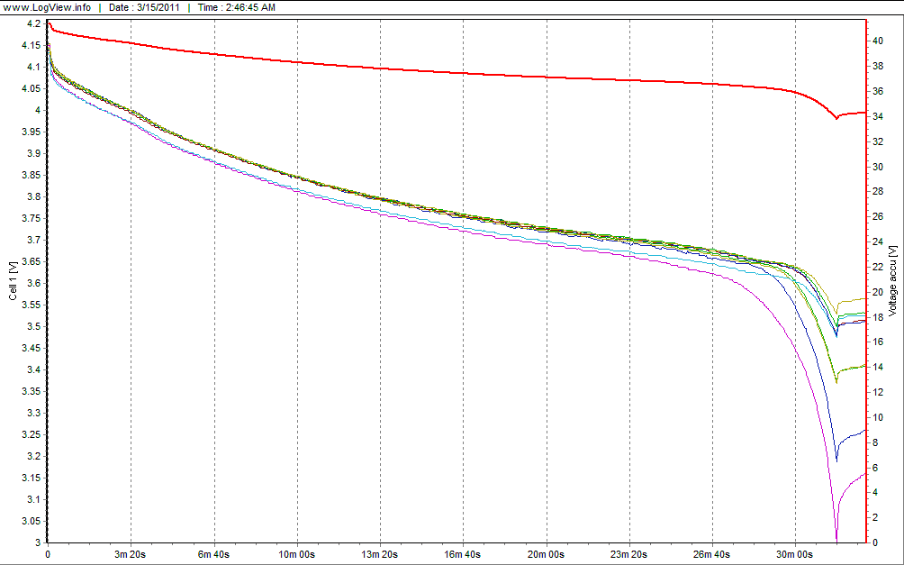
lipodisbalance.gif


^-- brand new turnigy 25C battery.

zippy discharge looks nearly identical.

You need to stop discharging at 3.6v (resting voltage) because that's when cell voltage starts to differ widely and rapidly.
That is only leaving about 750mAH in the pack.
 
wojtek said:
thanks a lot :wink:

my velomobile is waiting for one, prob HT but can't decide.. but crystalyte europe will only have them from 21 March.
They sell them at 180EUR for rear + controller at 195EUR.

Anyone based in Europe from ES planning to sell them?
http://shop.crystalyte-europe.com/home.php
 
thanks mighty volt!

yea i had no choice but to order from them... I would prefer to get it from one of the passionate ES member based in Europe but well...

Crystalyte Europe is OK, but not great in terms of customer service, replying to emails, shipping ect... I ordered my stuff on Monday [after the conversation with them that it would be shipped the next day] and they only shipped it on friday following my email.. Well.
Also they are based in Belgium so the customers are punished with 21% VAT!!!

Maybe i should start selling them , in Luxembourg we have 15% VAT only so already 6% savings!!!
 
@Spacey/Wojtek

I am the same. I would prefer to spend my money here but first off, its hard to get people to ship to Ireland, then there is the cost, then there is the customs and the general Roman Empire taxation that goes on.

Crystalyte-Europe offer the HT35-T for around €220 into my hands, not bad.

Plus I don't have to use Paypal.

One thing I wasn't sure from their site....when you order just the motor, is the controller included or is that just for people who order "Motor Kits".
 
you need to order controller separately.
Motor - 180EUR / sensorless controller 195EUR....
 
wojtek said:
you need to check the curve of the lipo cells. Each brand has a different discharge curve - for instance polyquest LP cells are pretty much flat all way down hence not really cool for ebikes. Anyway their prices are really high...

I actually have not seen any curves for turnigy / zippy but i think they are unlike polyquest. Im sure they are somewhere on the ES...


Yep, so true.

In early Lipo formulas, it used to be 3.7v nominal, and there was a little capacity to be gained by discharging down to 3.2-3.3.

In modern performance Lipo, 3.85-3.9v is nominal, and when you get to 3.5v, its effectly empty. Draining it further just causes wear on the cell in exchange for another 5% capacity or whatever.
 
itselectric said:
Well, this very much the same thing with our local customers, cannot decided HT or HS. So, I am hoping to make another video comparison this coming weekend. A race up hill between HS3540 and HT3525. My assumption is the HT3525 should go up hill better then HS3540 due to early torque delivery from the motor. We will see...watch for coming video....

Ken

Hey Ken, as with all cases of the same motor option with just a different winding, if you are going up a hill where both motors are running the controller at the current limit, then you will get a marginal amount more torque from the slower motor due to 2nd order effect. This is exacerbated a bit by the fact that the HT3525 has a slightly higher copper fill factor than the HS3540 (63 strands vs. 60 strands). However, if the hill is not steep enough to cause the controller in the low speed motor to run at its current limit, then the higher speed motor will do the climb faster hands down.

If the myth continues that the slower speed motor winding leads to a higher torque motor, then ARRG I will want to roll in a grave. Crystalyte is not doing the scene a favour by using a High Speed / High Torque naming convention. It should be HS/LS for high speed, low speed. Since speed is already implied by the last two digits (40 and 25 kph respectively), then it's redundant anyways and H3540 and H3525 would be better.

Then we just need to find something funny for the 'H' to stand for.

-Justin
 
Spacey said:
I mean there is no CA Cycle Analyst connector on the Sensorless Controller 40amp 72V, was hoping there was so I could maybe use it with my CA and lower the LVC cut off.

Hi Spacey, I just put a posting in a different thread showing the tap points for a CD-DP connector with the newer sensorless controllers:
http://endless-sphere.com/forums/viewtopic.php?f=2&t=26336

The throttle over-ride wiring is easiest done by shorting out R36 and then soldering a diode with the anode connected to the pad labelled SLA and the cathode connected to the green CA wire.

I'll arrange to have Kenny prepare a few samples with this CA-DP mod straight from China to make sure they can get it correct, and then hopefully it will be available direct from Crystalyte this way in the future.

-Justin
 
Hey, there's been quite a lot revealed already about the Crystalyte 'H' motor series here so I'll try not to repeat stuff, but did want to add some of my own observations and testing results from a few months ago in case people are interested.

Construction Style

The actual motor construction as many people have pointed out is exactly like the Nine Continent 205mm direct drive motor with 46 magnets and 51 stator teeth that is made by dozens if not hundreds of domestic motor companies is China. This is not a 'Crystalyte' motor in the same sense that the X5 was, but it is Crystalyte finally making use of the much more economic and power efficient design style, and then improving the mechanics to better fit western bike standards.

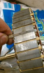
The rear motors have use a 35mm lamination stack, while the front hubs use a much thinner and lighter 24mm stator width. This is necessary for the front hub to be narrow enough to properly fit a disk brake.
View attachment 6

But it also means that the rear motors are 50% more powerful and have ~50% more torque output than the front hubs, and hence the front and rear options are NOT really motors of the same family. By comparison, the most common 9C hubs of this type have a 27mm stator width, sortof in between the front and rear Crystalyte 'H' motors. (9C also offer their motors in 24mm and 35mm widths, but most people ordering them for export get the 27mm.)

17mm Axle
The axle is 17mm diameter at the shoulder rather than 15mm which we see on 9C / Golden etc. This extra 1mm on the radius means that there is a lot more metal flat surface to go against the inside of the dropout. There is certainly no need for inside washers or spreaders:
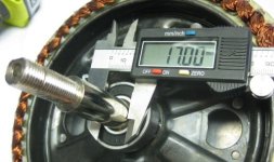
17mm Axle.jpg

Wire Exit
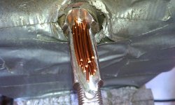
The wires for the motor exit a slot in the side of the axle rather than going through a hollow channel and coming out the end. This makes it WAY easier for attaching torque arms and changing around the axle hardware without having to snip off and reconfigure the connectors every time. The downside however is that it is a lot more difficult to waterproof, and this has been the demise of so many 400 and 5300 Clyte hubs. It looks like Crystalyte did a reasonable job of gooping and sealing the cable exit but only a season of wet weather riding will tell if this is effective:
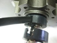
Wire through Axle.jpg

Freewheel Fit
This hub uses the screw-on freewheel rather than a cassette freehub, no surprise. The axle on the freewheel side of the rear hubs sticks out 39mm to the shoulder:
View attachment 3

That's enough to fit a 7 speed freewheel just fine:
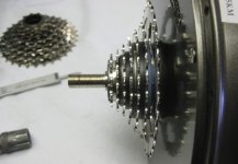
Freewheel On.jpg

However, an 8 speed freewheel will require a spacer washer:
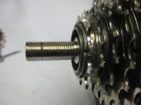
8 Speed Freewheel Space.jpg

Disk Fit
The best news for sure about these motors is the mount for the disk rotor. It's taken what seems like eons to get the chinese manufacturers to adopt an intrinsic 44m ISO bolt pattern for the disk rotors rather than the screw-on freewheel threads that used to be standard. However, in the case of 9C they only left ~15mm of caliper space between the rotor and side cover. Virtually all brand name calipers, especially hydraulic calipers, need at least 17mm or more of clearance. Both the front and rear 'H' Crystalyte hubs have an 18.0 mm standoff to the disk rotor mount, which is perfect:
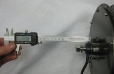
Front Disk Clearance.jpg

The spacing from the axle shoulder to the disk face also measured correctly (10mm front, 15mm rear), so you should be able to expect a drop-in fit with a disk equipped bike and not have to do any shimming or adjustment of the caliper.
 
Here is a picture showing the stator support change. The early prototypes that went out to retailers had a stamped steel support. The batch I received look like this


Another small change to note is the change from socket head cap screws to cross head. The fasteners are glued in so be very careful for the first half turn.

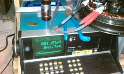
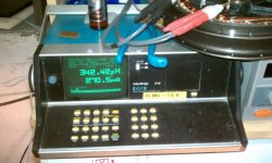
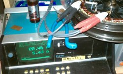
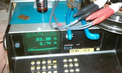
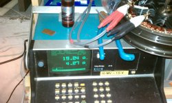
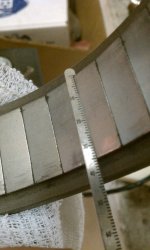
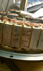
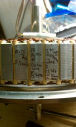
Here are some measurements that Luke took from an HS35 as well. These could come in handy..... (16khz)

-methods
 

Attachments

  • IMAG0935.jpg
    IMAG0935.jpg
    427.2 KB · Views: 14,328
  • IMAG0939.jpg
    IMAG0939.jpg
    422.7 KB · Views: 14,328
  • IMAG0940.jpg
    IMAG0940.jpg
    457.8 KB · Views: 14,328
  • IMAG0941.jpg
    IMAG0941.jpg
    469.6 KB · Views: 14,328
  • IMAG0942.jpg
    IMAG0942.jpg
    474.5 KB · Views: 14,328
Hall Sensors

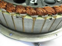
On the samples that we got, there were no hall sensors and at the time it seemed that Kenny was adamant that they were only available sensorless, which was to me a bit of a showstopper. However, the motor laminations had the notches for the hall chips:
Space for Halls.jpg
And methods had no problem getting Crystalyte to include them, so that is great.

Cogging Torque

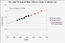
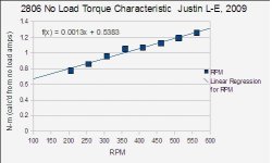
There has been a number of people asking about how much drag torque these motors have. Well, it's a fair bit. I tested between 200-600 rpm, and the result is pretty linear so we can surmise it starts off at 0.8 N-m from a stall and is more like 1.2 to 1.5 N-m over the RPM range of interest:
No Load Torque.jpg

That's pretty much exactly the same as the X5's. By comparison, the Nine Continent 27mm hubs have more like 0.8-1.0 N-m of drag at that rpm range:
9C Cogging Torque.jpg

All else being the same, we would expect 35mm 'H' series to have about 30% more cogging torque than the 27m 9C because it has 30% more iron and magnet width, but the actual cogging drag is 50% greater. So the hysteresis and eddie current losses are proportionally greater with this Crystalyte motor than with 9C. That could be because it uses stronger magnets, which at some point can greatly increase iron losses while only slightly increasing the output torque.

Dynamo Test Results

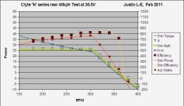
I independently tested all 4 of the motors (HS3540, HT3525, HS2440, HT2425) at both 36.0V and 48.0V on my dynamo using the Crystalyte 25A sensorless controller. I never got the 86% efficiency claimed by Crystalyte, it peaked at about 84% at 48V. In any case, the performance is pretty good and the measured output matches our simulator model spot on:
Dynamo HS3540.jpg

Initially I had the motors up there using the same naming scheme of XXYY where XX is the magnet width and YY is the turn count. However, now I've changed it around to be consistent with what Crystalyte has choosen, so if you go to
http://www.ebikes.ca/simulator
the options Clyte HS2440, Clyte HS3540, Clyte HT2425, and Clyte HT3525 all refer to these hubs.

-Justin
 
Justin,

which controller would you recommend ? (no sensors)
I don´t know if they´re going to sell only one sensored motor to a private customer.

Thanks,

Alexander
 
Luke is already up to his tricks.....

Apparently this is 15pcs of 14awg wire. Obviously he has been modifying the axle...

IMAG0946.jpg

Here is some of the same data confirming what Justin just posted but in a visual format (provided by Luke)

IMAG0948.jpg
IMAG0949.jpg
IMAG0952.jpg
IMAG0953.jpg

-methods
 
groundproximity said:
Justin,
...
Did you use sensored, or sensorless motors for research and testing?
...


justin_le said:
...
On the samples that we got, there were no hall sensors
...
-Justin

-methods
 
@ methods,

thanks - we must have pressed the submit button the same moment, that´s why :D
 
Back
Top