"Zephyr" - Finally, the "v4" Fechter/Goodrum/Hecker BMS...

Hi, i'm soldering the Zephyr already and have a general question about the connection of the balance cables in my 6p24s setup. I am going to build a balance cable setup, identically to a 6p parallel charging harness and to solder the cables directly to the board. But then i note the manual statementabout the importance of connection the balance leads at one time to the battery pack. I try to reduce the connections to a minimum. Therefore i don't like the idea of an additional connector.
Can i go further with my initial idea or is the additional connector important?
Thanks.
 
The only reason I recommend a connector there is to eliminate any drain for long term storage. If you fully charge the pack before an extended period of non-use, it should be good for at least 6 months. Periodic recharging during storage should prevent any problems.

Be sure to make all pack connections with the charger completely disconnected from the board.
 
Hey everyone,

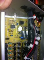
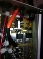
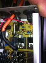
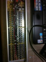
I've just completed my bms board and am not having any luck with the shunt lights for each channel lighting up.

i'm 100% that the shunt leds are installed correctly!


I've gotten the main led to go from red to green no problem by adjusting the pot

have i got something installed incorrectly somewhere ?

any help or tests i can try would be great...

i've tried adjusting voltage higher or lower ... and still no luck with the shunt leds turning on... also the bms is not enabling the batteries to be charged at all

thanks
-steveo
 

Attachments

  • bms2.jpg
    bms2.jpg
    90.7 KB · Views: 3,040
  • bms3.jpg
    bms3.jpg
    70.9 KB · Views: 3,049
  • bms4.jpg
    bms4.jpg
    81.1 KB · Views: 3,049
  • bms5.jpg
    bms5.jpg
    85.9 KB · Views: 3,049
Nice looking build.

You can test the cell circuits individually with a current limited power supply. Feed voltage to the tap wires and dial it up slowly while watching the current. If your power supply doesn't have enough voltage to run all the channels, do a few at a time for testing.

If you don't have a bench power supply, you can use a light bulb in series with a Meanwell as a current limited supply.

I strongly recommend doing initial testing with no cells attached. With no cells attached, there is no charge current and the EOC detection will kick in and terminate the charge. Remove the jumper to disable EOC for this test.
 
fechter said:
Nice looking build.

You can test the cell circuits individually with a current limited power supply. Feed voltage to the tap wires and dial it up slowly while watching the current. If your power supply doesn't have enough voltage to run all the channels, do a few at a time for testing.

If you don't have a bench power supply, you can use a light bulb in series with a Meanwell as a current limited supply.

I strongly recommend doing initial testing with no cells attached. With no cells attached, there is no charge current and the EOC detection will kick in and terminate the charge. Remove the jumper to disable EOC for this test.

Hey fechter

do you mean power the bms via the balancing wire tabs?... for example ... i can try to use a 30v power supply that has the current limiter board on it ... and power say ... 8channels.... slowly bring up the voltage with current low say 1-2 amps and the leds should light up once each channel see about 4.2v?

to confirm .... i place power to the most negative balance wire tab, and the most positive for the 8th cell on the balance tab ... is this correct..

so to be clear i only apply power from balance tab only to test channels?

if you have any photos ... or some paint skills to illustrate that would be appreciated...

thanks

-steveo
 
steveo said:
do you mean power the bms via the balancing wire tabs?... for example ... i can try to use a 30v power supply that has the current limiter board on it ... and power say ... 8channels.... slowly bring up the voltage with current low say 1-2 amps and the leds should light up once each channel see about 4.2v?

to confirm .... i place power to the most negative balance wire tab, and the most positive for the 8th cell on the balance tab ... is this correct..

so to be clear i only apply power from balance tab only to test channels?

if you have any photos ... or some paint skills to illustrate that would be appreciated...

thanks

-steveo

Yes, correct. Bypass the control circuit altogether this way. You can do good tesing at 100mA. I would not go over 500mA for testing. This is just to test the cell circuits.

Yes, I need to revise the testing instuctions badly. It's way too complicated right now and needs better diagrams. It's on the to-do list.
 
Ive done the testing best i could with my charger set at 100mah

http://www.youtube.com/watch?v=v73K6OrJ8AE

Any further tests?

Thanks for your help!
-steveo
 
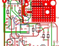
Hello, i'm next to finish the assembling of the board, but yesterday i recognized the resistor R15 with 1k and R14 with 100 Ohm on the board. But in the BOM is only R14 with 1k. Should i get a 100 Ohm resistor for R14 on the board? Furthermore the electric schematic of the charger control in my instructions is wrong. After charger conection should be first the fuse and then the diode. On the board is first the fuse and then the diode.
I hope i get finished this week and can start next week with testing.

Thanks Martin
 
Hello GregB,
when you look at the very first picture of the board in this thread you can see R15 at the throttle connection (down left) with 1k and R14 with 100 Ohm (in the middle of the charge control board). I soldered the 1k resistor in the r15 place and then searched for the 100 Ohm resistor for R14. Now i have at least one 1k Ohm or 100 Ohm resistor missing.
 
mj2412 said:
Hello GregB,
when you look at the very first picture of the board in this thread you can see R15 at the throttle connection (down left) with 1k and R14 with 100 Ohm (in the middle of the charge control board). I soldered the 1k resistor in the r15 place and then searched for the 100 Ohm resistor for R14. Now i have at least one 1k Ohm or 100 Ohm resistor missing.

i believe there is a typo on the pcb board


r14 shows as 1k; however it should be 100ohms

r15 is 1k

-steveo
 
R14 (going to the main FET gate) should be 100 ohms.
R15 (throttle interface) should be 1k.

Yes, the schematic is wrong in the fuse area. I'll send you the corrected version.

My layout file for the board shows R14 marked 100. I'm not sure how that got messed up.
What version number is printed on your board?
 
I will check the version back home (The board layout looks like the actual one at the first page). But with R14 100Ohm and R15 1k Ohm the board is right. The mistake is in the BOM, because R15 and R14 are messed up.

I will get a 100 Ohm resistor and solder it into the R14 place.

Thanks for all the help.

Martin
 
fechter said:
R14 (going to the main FET gate) should be 100 ohms.
R15 (throttle interface) should be 1k.

Yes, the schematic is wrong in the fuse area. I'll send you the corrected version.

My layout file for the board shows R14 marked 100. I'm not sure how that got messed up.
What version number is printed on your board?

mine is 4.4.3 which i believe is the most current version

i also noticed another typo somewhere in the channels where the resistors where... i think instead of 220ohms if was like 470ohms

-steveo
 
Any idea when these will be available? Or if anyone has one unassembled/unused?
 
well that's great my board doesn't even have this new R14 position on it. better check yours Zenid. Looks like I will have to cut track and mount on underside of board.
 
Gregb said:
well that's great my board doesn't even have this new R14 position on it. better check yours Zenid. Looks like I will have to cut track and mount on underside of board.

Yours should look like this. If not, tell me the version number.

R14 location is circled in blue

r14 location.jpg
 
Interesting. I don't think I have a copy of that file.

Actually, it will probably work fine like that without the resistor. It would only be a problem if you were running max current and had lots of inductance in the wiring. The switching frequency is very low so ringing can't build up.
 
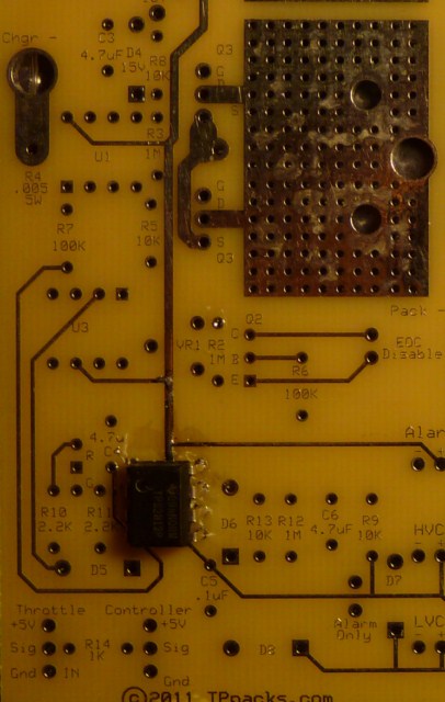
That whole section of the board is completely different on mine (v4.4). U3 is horizontal, rather than vertical as in the documentation, and R14 on mine is the 1K one that goes between the signal wire I/O for the throttle cable. In the documentation, this got renamed "R15", and that R14 in the doc doesn't seem to exist anywhere.

control-sect-empty-640x480.jpg


If - like you say - that isn't important then OK. But I will probably add that extra FET and up the charge rate at some point. Are you sure this won't be a problem when I charge at close to its limit?
 
I fixed my pot and I'm nearly there calibrating the EOC cutout, but it's proving tricky to get it just right so that all the LEDs are lit before it cuts out - A fraction to far right and not all of them light up, and a fraction too far left and it never shuts off at all. I'm using resistance readings of that pot to slowly hone in on the exact right setting in ohms, and I'm almost there... :)

I've given it a good few runs and recharges now and I'm delighted with the vastly improved recharge rate I get with my 9A charger. It's 3 to 4 times quicker than my old SLA charger. Details of my (near) final arrangement here:
http://endless-sphere.com/forums/viewtopic.php?f=10&t=29790

Another minor issue I'm having is I still have a problem with the main LED. After whatever killed my U3 chip happened, I never saw it light up red or orange again. When I did a diode check before, it would glow briefly red or green depending on which leg I touched, now the green will light up, but nothing on the other leg. Does this mean it's definitely the LED, or could a short be elsewhere meaning I should lift the leg to make sure?
 
Yes, the adjustment will be touchy with no cells attached. I think you should set it a little high (to the right) to ensure it shuts off.
It is not necessary for all the LEDs to light up during a normal charge cycle as well. As long as charger voltage is set close to the threshold where they light up, the cells will be getting full charge. If you crank the charger voltage higher, they will all light up, but you'll have a lot of heat coming off the shunts near end of charge. The idea is to minimize the heating.

On the red LED, try measuring the voltage on the end of the resistor that feeds it (R10). Measure the side away from the LED. You can temporarily jumper the HVC line to make sure the red part is supposed to be on. You should see around 12v on the resistor when the LED is lit.
 
Hey Fechter,

are there any other tests i can try ?

I have posted a quick video of the bms testing you where telling me to give a try. (a few posts back)

thanks
-steveo
 
fechter said:
It is not necessary for all the LEDs to light up during a normal charge cycle as well. As long as charger voltage is set close to the threshold where they light up, the cells will be getting full charge.
I've been testing "live" as I've been using the bike and recharging the bank over a number of short cycles. I was assuming that any LEDs that were unlit would indicate cells that haven't yet fully charged and have been trying to get it so they all are lit before it cuts out.

Measuring the voltages on the cells, though, they all seem to be reasonably close, typically 'settling' to within 0.05V of one another.

I'll try what you suggest with the red LED. Thanks. [EDIT: Voltage checks out. Red is dead...]
 
Zenid said:
I've been testing "live" as I've been using the bike and recharging the bank over a number of short cycles. I was assuming that any LEDs that were unlit would indicate cells that haven't yet fully charged and have been trying to get it so they all are lit before it cuts out.

Measuring the voltages on the cells, though, they all seem to be reasonably close, typically 'settling' to within 0.05V of one another.

I'll try what you suggest with the red LED. Thanks. [EDIT: Voltage checks out. Red is dead...]

OK, good you found the problem with the red LED. Easy enough to fix that.

If you like seeing the cell LEDs light up, you can crank the charger voltage up slightly. As long as the cells are reaching the set point, the LEDs don't really need to light up. This would indicate all the cells are well balanced. If an imbalance occurred, you would see the high cells light up.

You can also crank up the shutoff current a little to ensure it shuts off. When the current gets below 200mA or so, the cells are mostly full and charging them more may actually reduce cycle life a little.

It sounds like you have it pretty close to dialed in now. The fact that it doesn't get buring hot at end of charge is very good also.
 
Back
Top