"Zephyr" - Finally, the "v4" Fechter/Goodrum/Hecker BMS...

I agree, the test instructions could be better, but I must say, this was never intended to be a project for "first-timers", so to speak. Nonetheless, the whole point of this thread is to provide help for those who are putting one of these together. The big problem with this is that although this board will work with a very wide variety of configurations and charging setups, each one of these might operate a bit differently, in terms of how the circuits operate. It makes it hard to have a "complete" set of testing instructions, covering all possible cases.

In the next version of this, which Richard and I are working on right now, we are using a new control scheme that should work the same way with virtually every setup. The end-of-charge detection logic will work the same way, for all setups, and there's no "adjustments" required. The circuit is simpler, with fewer parts, because we were able to eliminate the current measuring portion of the circuit. Anyway, this should help simplify the testing instructions for these new variants.

Gregb said:
when you charge money for things, you have to keep it up to date

You make it sound like we are making money off of this stuff. :lol: The "profit" from these boards is about $5. Even if the margin was $100 a board, I'd have to sell literally hundreds of these in order to come close to making up what I've spent on test boards and unsold older versions. :roll: Also, the website is still down because I have been concentrating on these new versions, plus the related "Lite" variants, and haven't had time to build a new website.

Anyway, if you have a problem with a setup, post as much detail as possible here, and we'll all try and figure out what is going on.

-- Gary
 
Quite right, I agree the instructions are not very good.
If you have any problems figuring out the testing procedure, you can ask here or pm me.
 
Sorry Gary was not inferring you were making money or or being duplicitous. apologies if it came out that way. Some time ago I sent fechter a reference to a SM technology lifepo charger from Microchip. I have been busy lately on volunteer things for handicapped people and haven't been able to give it any time, but have you considered changing your philosophy slightly? Give away the shunt method, but keeping your control panel use it to switch on individual channel chargers when one channel hits full on bulk charging which would then be turned off. If they built a version on a more useful package size I would have tried it myself. You have hinted that SM technology is available to you. I bought one of their test boards and it performed well with accurate cut off voltages etc but I don't have the tools to mount them. The chips are very very cheap and the specs are pretty impressive.

regards
and apologies if necessary

Greg
 
Yes, I've looked at dozens of chips and so far the best ones I've seen are the Seiko ones. It's still on the drawing board, but we want to get a solid through hole version first. I'm not so good at hand building with those microscopically small smd components. The capacitor coupled balancing scheme still has potential too, but will take a lot of time/money to get built and tested. This would avoid the need for shunts and all that wasted heat.
 
Yeah. Goodrum & Fechter are spending too much time on luxury cruises, and lounging around in gold-plated swimming pools off of all the money they made... :lol:

Come on guys! We want one of these right away:

gfbmsdummies.jpg


Seriously though I will eventually get round to doing a test section on my site, complete with the usual pretty illustrations and photos. I'm just a little swamped right now...
 
Yes, the surface mount stuff is an attractive future option, mainly because of the reduced footprint and the possibility of being machine-assembled. With these two new (16 and 24-channel...) Zephyr variants, we have addressed both issues, however, by borrowing from the "Lite" variants I'm still working on for LiPo setups. What we did was switch to using resistor arrays and use quad versions of the opto chips. These two changes alone have significantly reduced the build time and the parts count, for a typical board. For example, it used to take me literally hours, just to bend the leads, install, solder and trim the hundred, or so, resistors used on a typical 12-channel board. With the use of the arrays, the time to install the equivalent number has been reduced to about 15 minutes.

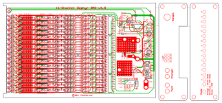
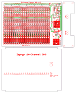
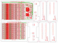
The use of these arrays also allows us to really reduce the footprint of both the 16 and 24-channel versions, as you can see below:

16-Channel Zephyr BMS-v4.4.8n.png

24-Channel Zephyr BMS-v4.4.8m.png

Both are now sized to fit in a single Hammond extruded aluminum box, the 4.06" x 6.3" version for the 16-channel, and the slightly larger 4.74" x 6.3" variant for the 24-channel board.

There are now three opto busses, LVC, Any HVC and All HVC. The reason for the two HVC lines is that the Any HVC optos are connected, like always, in parallel. The All HVC set of optos are connected in series, so it doesn't trip until all the shunts are finally on, which says all the cells are full and balanced. The new charge control logic uses this All HVC signal to trip the end-of-charge (EOC) shutoff logic. The any HVC signal, which trips at a slightly higher point than the All HVC signals, is used to cycle/throttle the charge current, just like on the current Zephyr variants. This provides for HVC protection for errant, or grossly imbalanced cells.

We just finished these layouts, and they are being turned in for a test run on Monday. Richard will be testing a 16-channel version with his 16s5p a123-based LiFePO4 setup, and I'll do a 24-channel version, to try with one of my LiPo setups. I've already been testing the new control logic, with the Lite variants, and the basic cell circuits are pretty close to what we've been using for some time, so we really don't expect much in the way of surprises. Anyway, I will post our progress here.

-- Gary
 
Please, please, please, get away from this through hole plated technology. Just had a faulty FAN and getting the components out for fault finding is impossible. By all means use double sided boards (you have to) but solder both sides of any through connection..... and some of the track- hole spacing is a bit tight and allows solder across.... :?
 
We don't really have an option on the through hole plating unless we go to another board house. If the holes were slightly larger, removing the parts would be easier. I use a desoldering station and that works great for getting parts out in one piece. You can always cut the legs off a part and remove the legs separately, then clear the holes.
I try to avoid close spacing wherever possible to make soldering easier, but there are going to be some tight spots no matter what.

Always hold the board up to a light after soldering to inspect for bridges. When the board is back lit, any bridges will be pretty obvious.
 
I've done quite a bit of parts replacement, with all the test versions we've done, and I use an inexpensive solder sucker/vacuum device, from Radio Shack, to clear the holes. Works great. :)

I've been finding solder bridges to be much less of a problem since we started using these resistor arrays, which have legs that don't need trimming. Also, having the main traces on top helps a lot.

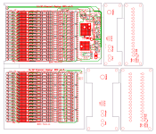
Here's our latest variant, which is now a single PCB that can either be 16 or a full 32 channels:

32-Channel Zephyr BMS-v4.4.8x.png


The 16-channel version fits in a 4.06" x 6.3" by 1.2" extruded aluminum box, and the 32-channel version is sized for the taller 2" version of the same box.

-- Gary
 
@GGoodrum- Have you decide the pre-made BMS?
 
since the link to tppacks does not work do you still have any boards in stock and how much?
 
Sorry, I missed that. I'm going to try and make the website a priority this weekend, but in the meantime, you can send me a PM. If I were you, however, I'd wait for another week, or so. Monday I am turning in our latest version of the newer, easier to build Zephyr variant, which makes use of resistor arrays and quad opto chips that drastically reduces the build time.

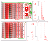
32-Channel Zephyr BMS-v4.4.8z.png

This latest board will support up to 32-channels, in a single box. For sixteen channels, a 1.2" x 4.06" x 6.3" box is used, and for the full 32 channels, both boards go in the taller 2" version of the same box.

Functionally, this is the same as its been for a the last several versions, as we've been mainly tweaking the layouts. There's three opto lines, one standard one for LVC, and two for HVC, one set a bit higher than the first. The higher one is used as a failsafe, to catch any weak/errant cells that may reach the normal cutoff way before the rest of the cells. This will trigger the HVC cycling mode where the power will cycle between off and on about once a second, until the rest of the cells get closer. The other HVC opto output string is connected in series. This signal goes active when all the cell's bypass circuits are on, which means the cells are all full. This then causes the EOC logic to shut off the charge current and turn the main LED a solid green.

Stay tuned...

-- Gary
 
that's ok for now ggoodrum budget (i am recovering stuff lost or damaged by this year's floods on the east coast caused by a week of off and on rain and i am trying a couple other ideas using a pair of meanwell power supplies and 10 voltphreak chargers.

the temporary house i am in has a bad outlet that caused 2 soneil chargers to blow and take $300.

also will the failsafe mode eliminate the effect that seems to occur on the negative end of the pack where the end 4 cells seem to be slightly lower than the rest?
 
"also will the failsafe mode eliminate the effect that seems to occur on the negative end of the pack where the end 4 cells seem to be slightly lower than the rest?"

Could you elaborate on this? Do they measure a lower voltage? and by how much ? and does this effect come in after standing for a while or are they cutting off early ?
None of mine are exactly the same particularly after an hour or so. and are you leaving something like the cell log across them ? It does consume power
 
Gregb said:
"also will the failsafe mode eliminate the effect that seems to occur on the negative end of the pack where the end 4 cells seem to be slightly lower than the rest?"

Could you elaborate on this? Do they measure a lower voltage? and by how much ? and does this effect come in after standing for a while or are they cutting off early ?
None of mine are exactly the same particularly after an hour or so. and are you leaving something like the cell log across them ? It does consume power

This was with the original v2.x boards, which had a tap for the 12V regulator off the top of the 4th cell. All of the v4.x variants have the regulator powered from the whole pack voltage.

-- Gary
 
Here is the latest layout variant, that we just turned in to run:

32-Channel Zephyr BMS-v4.4.9.png

Functionally, it is the same, but we've made some accommodations so that this one PCB can support 12s, 16s, 24s and 32s configurations. Also, I think we are a lot closer now to having a final variant. After Richard finishes testing this one, we should be good to go. :)

-- Gary
 
Hey,

I bought the board very early around the 11th page of this thread, and I am wondering if the board I have is good enough to trust with A123 20Ah worth of 7000$...

I never had the time to put together after I ordered the board and the parts.

Is there anything that has changed significantly since I bought the parts and board? I will be putting it together soon and if you are telling me it it's no use to put it together due to problems with the original design then I won't lose time with it.
 
The addition of the diode described on the previous page is about the only major thing. There were a few mismarks on the actual board for the components, so when in doubt, check the schematic. The schematic is correct. I'll send you the updated schematic. The testing instructions suck. Zenid's version will help. Building this board is not a good project for a beginner or someone with limited electronics knowledge.
 
Gary,

Would I be able to use non standard cell numbers, like 26s, 28s and 30s in the 32s "BMS"?
 
Yes, any number of cells can be used. A single jumper would need to be installed for non-standard cell counts.
 
fechter said:
Building this board is not a good project for a beginner or someone with limited electronics knowledge.

I have good knowledge(I think), I just got off the forum for a while because I moved house and had to renovate(not done yet)

Do you guys sell pre-built and tested boards?
 
I also didn't read every post in this very long topic and have the same question and I also wonder about the price.
 
Would really help to have costs simply displayed etc and also how this BMS differs from the normal Chinese BMS etc

35 pages is a lot to wade through, I am interested in a 16 cell one but have no idea on price/build/info
 
One technique to solve these problems is for the thread owner to edit the first post to contain a summary of the info. Folks coming to the thread get up to speed, more or less, in the first posting. When that post is updated a posting can be added to the thread to let folks following the thread know they might want to go reread the first post for the updates, or the updates can be summarized in the thread.
 
Back
Top