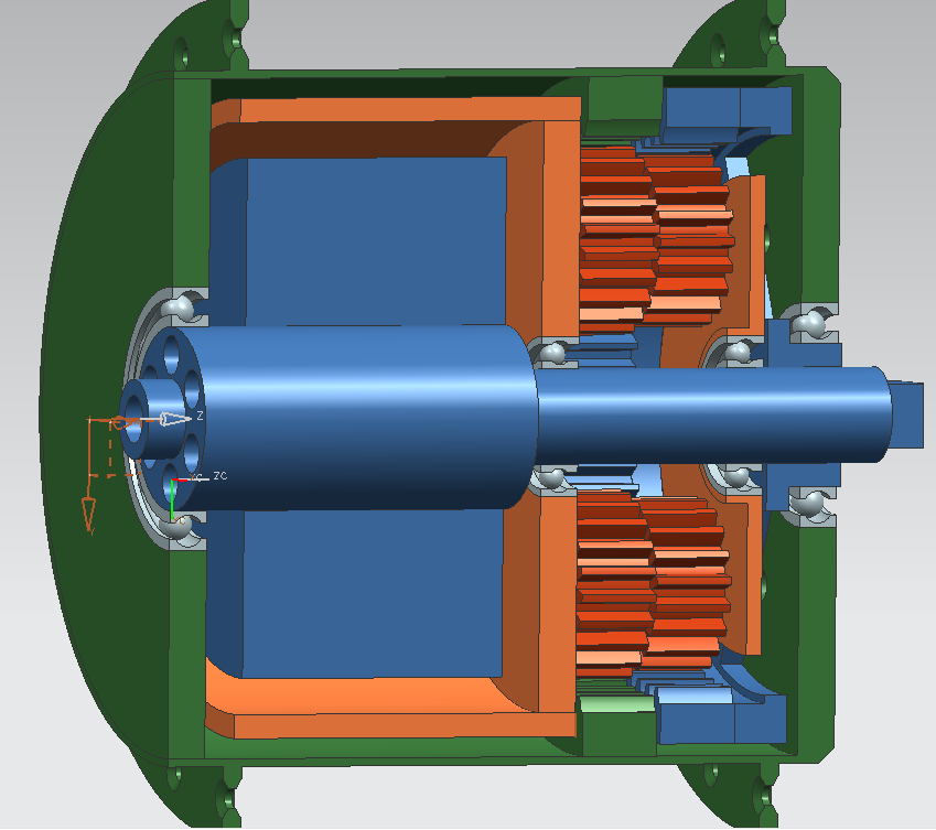
RC-Type Hubmotor

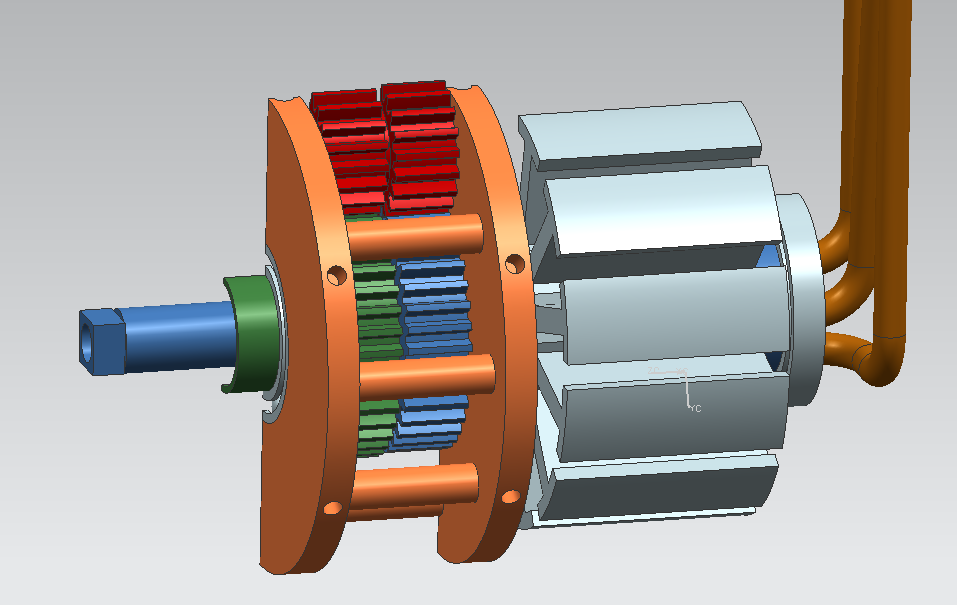
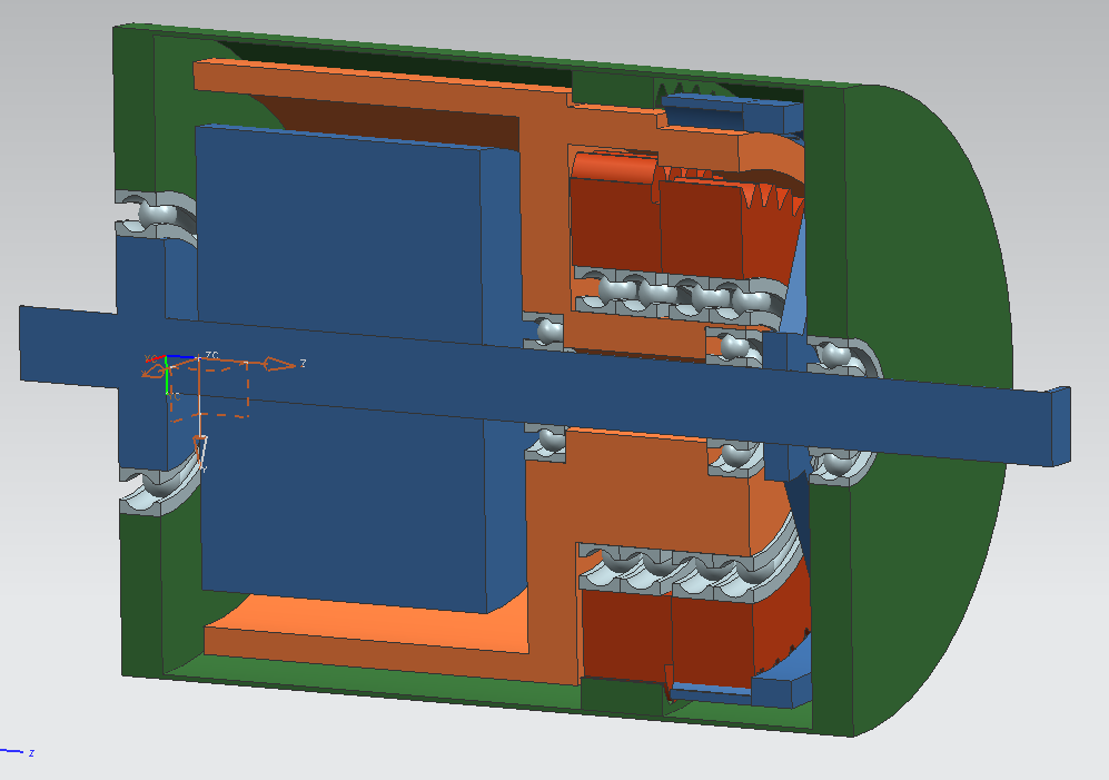
The teeth forces in this configuration are very high, as I already mentioned, a ring gear version would have to cope with less stresses. Sadly the design isn't as clean:

ring%20gear%20hub2.png


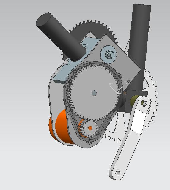
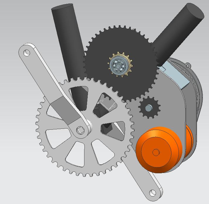
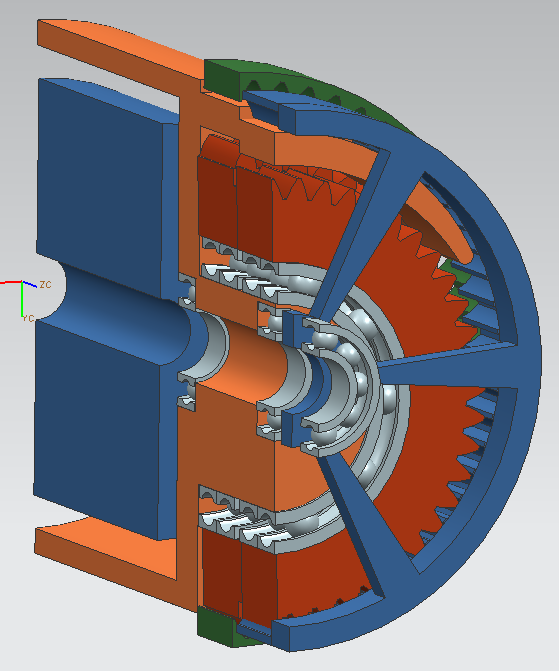
another approach is to use a single planetary doublegear with very little offset:
eccentric_hub_drive.png

eccentric_hub_drive2.png
 
I'm curious about the construction. Will you be buying standard gears or fabricating them yourself? In the former case, from where? In the latter, how?
 
I think it would be a nightmare trying to get that offset configuration dynamically balanced......

That's right, even the "regular" version above will take much time for that. I will only build the first version this year, and see if the gears survive. But in my opinion the ring gear, single planet version will survive the longest time. But I'm not sure yet.

Will you be buying standard gears or fabricating them yourself?

I will buy them from maedler. I will use the cheap 11SMnPb30 Steel gears with module 1. But I think the won't be strong enough but I will give it a try. Maximum Force per tooth is about 450N. The cheap gears only last till 100N steady and cost around 10$ per piece. The stronger hardened 16MnCr5 Steel gears last till about 1000N per tooth steady, but cost about 50$ per gear. If the cheap gears won't last long I first will stick to the ring gear version or search for a even cheaper source for hardend gears.

With the ring gear version, it's hard to implement the free wheel clutch because it already a squeezed design. With the spur gear version this is simple, I can just add it between the central blue shaft an the blue fixed gear. My todays version has larger central gears and 8 planet gear pairs to get the tooth forces down (less arm of lever).

updated version:
blue=37t
green=38t
planets: 18t and 19t
reduction ratio: 12.89
my lathe can only be fed with pieces smaller than 40mm in diameter, so that seems to be the largest gears possible for it.
ring%20gear%20hub3.png


Here is the link to the english version maedler webpage: http://www.maedler.de/Product/1643/1618/1034/1076/1079/1083.aspx

Oops.. I just saw they don't sell 19t gears :evil:

What's still missing is the hub housing itsself. I don't wont to spend a hundret bucks for a working hub and destroy it :(
 
For anyone who wants to play with the numbers for this configuration, here's a spreadsheet:
 

Attachments

  • crossbreak's gearing rev.1a..ods
    9.8 KB · Views: 228
  • crossbreak's gearing rev.1a (Excel format).xls
    7.5 KB · Views: 151
Thanks for that sheet Miles! That's really helpful. When using that sheet, one has to note that #fixed+#planet 1=#output+#planet2.
Otherwise the gearbox isn't concentric.
I'm now waiting for my Turnigy 80-85, to see if everything will fit before I order the new can pipe and the gears. Does anyone now a source were it's not in backorder? I haven't looked through the supply thread yet, maybe I'll find an other source there.

Thanks for all that help I got, I will report, when I get to work!
 
crossbreak said:
When using that sheet, one has to note that #fixed+#planet 1=#output+#planet2.
Otherwise the gearbox isn't concentric.
I thought of having only two inputs with an auto 1t offset for each but it seemed less flexible.

crossbreak said:
I'm now waiting for my Turnigy 80-85, to see if everything will fit before I order the new can pipe and the gears. Does anyone now a source were it's not in backorder? I haven't looked through the supply thread yet, maybe I'll find an other source there.
Isn't that line being replaced by a different one?

Ref: http://endless-sphere.com/forums/viewtopic.php?f=30&t=30077
 
Added "step" factor (in practice, this will only be set to either 1t or 2t difference). Only the "fixed" and "Planet 1" tooth counts need to be entered.
 

Attachments

  • crossbreak's gearing rev.1c. (Excel format).xls
    8.5 KB · Views: 120
  • crossbreak's gearing rev.1c..ods
    10.6 KB · Views: 130
Thanks a lot for all of your help!

Since I could not get a 80-85, I got a 80-100 for the rear drive. The Hub-Motor project will proceed next year. I will open a new thread for this project when I start working next month, I'm still waiting for some parts.

Here are some CAD pictures. The mjaor work is done I think. Reduction Ratios: 1st gear: 30:1, 9th gear 9,5:1

by2whfi1xcnirzzv8.jpg

by2wlcim3eaxl761g.jpg

by2wlk9z6qdk2wkt0.jpg
 
no, I got the older, heavier version without slots at the end. Maybe I drill those slots in mine for better cooling. Disassembly was easy with the pictures fromm the "rewind 80-100 thread". I think I'll rewind mine, too, to get rid of one reduction drive (the middle chain drive).
I'll need a KV of 42, guess that rewiring it with 15 wires per coil, each 1,2mm in diameter will do the job, if connected in STAR config.
 
That looks like it will work well for everything, except the bicycle chain at high speed on the second reduction stage.

I would strongly recommend going to a chain designed for high speed operation, like #219. Bicycle chain just doesn't tend to last well at 10x the speed it was designed to operate.
 
I want to solder the 80-100-KV130 Outrunner in STAR, so I get the 75KV.

Very nice design ! But by solder the 80-100-130kv in star it is possible to get 75kv, can someone please explain how ?
 
Very nice design ! But by solder the 80-100-130kv in star it is possible to get 75kv, can someone please explain how ?

-The 80-100-130kv has 8 turns per coil that are wired in DELTA, so the "return wire" of Phase A is connected to Phase B (forward wire), the return wire of B with C and of C with A.

-If You now wanna wire it in STAR, you have to devide your phases in forward and return wire and wire all three return wires to a short circuit point outside the housing (inside is a more difficult job).

-The KV will be reduced by sqrt(3) so 130/sqrt(3)=75 the torque will rise in the same manner.

I yet don't really know how to seperate forward an return leads.Turning the rotort to induce currents in the coils "by hand" should be possible. The seperated wires would be short circuit by good guess with an old fashioned analog current meter. If current flows, the wires are of the same phase.

But that way I won't know which one's forward and which one's return lead :? . Any ideas to identify them is welcome.
 
ok, the clue is to connect everything in a triangle.

Take one winding (lets call this one 1), this is your reference. Spin motor (drill press ?) and measure AC voltage accross this
winding using normal multimeter (in the AC setting !!!!).

Take another winding (2 ?) and connect it to the first one in series. Measure the total series AC voltage. I know it sounds a bit
strange but the total series AC voltage should be equal to the AC voltage of a single winding. If you measure around 1.7 times the
voltage of a single winding then reverse the connections of winding 2 to end up with an AC voltage equal to that of a single winding.

Now connect the third winding (3) in series with 1 and 2 and measure the AC voltage again. If you measure 2 times the voltage
of a single winding, reverse the connections of winding 3. If the total AC voltage of the three series connected windings is 0 then
you've connected everything in the correct order. You can now short the start of winding 1 with the end of winding 3 (remember,
the voltage was 0 so this is no problem).

Now you got your 3 windings connected in delta.
 
Take another winding (2 ?) and connect it to the first one in series. Measure the total series AC voltage.
That's the trick. Too easy! Thanks for your help!

Keep it on topic, please.

sorry for that, maybe i should open a new thread. But it's already completely OT.
 
Back
Top