But just to be funny I'd probably paint a pineapple-line pattern on the thing. 
You are using an out of date browser. It may not display this or other websites correctly.
You should upgrade or use an alternative browser.
You should upgrade or use an alternative browser.
Li-Ion Pack Build From Scratch For CrazyBike2
- Thread starter amberwolf
- Start date
I had a sudden thought earlier while pondering where I might have put the old scrap wire I was going to use to solder these up in 1P sets, and decided to try it first.
I've got some thick (7-8mm/10mm x 20mm or so) aluminum bars nearly two feet long that used to be part of an old Sony VTR system, with holes predrilled and tapped in them, and some scraps of wood, and clamps, so I screwed one bar solidly to the wood, and a second bar thru the two large untapped holes with bevel-head woodscrews, so that the action of tightening them down would help clamp the bar in place, providing tension against the other bar, thru whatever I put between it.
Of course, it's not *enough* tension, so I got out my clamps, and tried them out. Naturally, I'm being extra stupid today, so I put the all-metal C clamp on there, too, directly across the bars, which are the busbars to get power to the cells clamped between them.
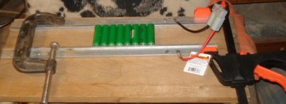
I did not even realize this was stupid until I put it on the Sorenson, and it hit the current limit of 1A I'd set, and showed zero volts, when it was set to 4.1V. I stared for few seconds and then panicked when I realized what I'd done. Man, I'm just dangerous these days.
I took that clamp off and as it isn't wide enough to put any insulators between it and the bars, I just went with the plastic-padded bar clamp I got free with a coupon at Harbor Freight. It's crappy, but it does work for this purpose.
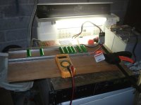
Still, the cells don't all fit tightly enough against the bars unless i put some fo them at slight angles, due to the leftover tab-weld bits left on some of the cells by their original owner. (I wish the tabs had just been cut rather than removed, but that's life).
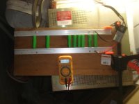
To verify the cell connections, I measured from ground busbar to the positive cap of each cell (whcih sticks up just enough from the positive busbar to be able to touch a meter probe to it). If it was a poor connection at negative end or both ends, it would read 0V. If poor at positive end, it would read just cell voltage. If ok at both ends, it would read the same as the positive busbar.
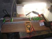
I charged it for an hour or so at that 1A limit, which is about 125mA per cell (assuming they are sharing evenly, which they probably aren't). They rose about .3V in that time. I'm using the 8 3.2-3.3V cells for this test, so they're about 3.5V at that point.
I turned up the current limit to 2A, and waited a few minutes, verifing that cells are still room temperature. Turned up to 4A, waited a few minutes, and still at room temperature. Voltage on each cell is still equal between them all, within a hundredth of a volt, at what should be 500mA current thru each cell.
I'll be frequently checking the cells over the next hour, to see how well they charge, and if there are problems or not. If all goes well, I'll start the next group, let these sit unconnected, and recheck their voltages to ensure they aren't dropping as they sit, and marking any that don't keep their charge.
I've got some thick (7-8mm/10mm x 20mm or so) aluminum bars nearly two feet long that used to be part of an old Sony VTR system, with holes predrilled and tapped in them, and some scraps of wood, and clamps, so I screwed one bar solidly to the wood, and a second bar thru the two large untapped holes with bevel-head woodscrews, so that the action of tightening them down would help clamp the bar in place, providing tension against the other bar, thru whatever I put between it.
Of course, it's not *enough* tension, so I got out my clamps, and tried them out. Naturally, I'm being extra stupid today, so I put the all-metal C clamp on there, too, directly across the bars, which are the busbars to get power to the cells clamped between them.

I did not even realize this was stupid until I put it on the Sorenson, and it hit the current limit of 1A I'd set, and showed zero volts, when it was set to 4.1V. I stared for few seconds and then panicked when I realized what I'd done. Man, I'm just dangerous these days.
I took that clamp off and as it isn't wide enough to put any insulators between it and the bars, I just went with the plastic-padded bar clamp I got free with a coupon at Harbor Freight. It's crappy, but it does work for this purpose.

Still, the cells don't all fit tightly enough against the bars unless i put some fo them at slight angles, due to the leftover tab-weld bits left on some of the cells by their original owner. (I wish the tabs had just been cut rather than removed, but that's life).

To verify the cell connections, I measured from ground busbar to the positive cap of each cell (whcih sticks up just enough from the positive busbar to be able to touch a meter probe to it). If it was a poor connection at negative end or both ends, it would read 0V. If poor at positive end, it would read just cell voltage. If ok at both ends, it would read the same as the positive busbar.

I charged it for an hour or so at that 1A limit, which is about 125mA per cell (assuming they are sharing evenly, which they probably aren't). They rose about .3V in that time. I'm using the 8 3.2-3.3V cells for this test, so they're about 3.5V at that point.
I turned up the current limit to 2A, and waited a few minutes, verifing that cells are still room temperature. Turned up to 4A, waited a few minutes, and still at room temperature. Voltage on each cell is still equal between them all, within a hundredth of a volt, at what should be 500mA current thru each cell.
I'll be frequently checking the cells over the next hour, to see how well they charge, and if there are problems or not. If all goes well, I'll start the next group, let these sit unconnected, and recheck their voltages to ensure they aren't dropping as they sit, and marking any that don't keep their charge.
liveforphysics
100 TW
I love the clamp shorting! Classic! I hope you scrapped that batch that got shorted.
karma
10 kW
i use these cells for my diy camcorder pack i charge at 2 amp with no problems or heat :wink:
Fortunately the cells themselves didnt' get shorted during the metal clamp incident; they werent' fitted well enough between the rails for anythign to happen to them. I got lucky.
I would probably have noticed the stupidity much earlier if they had been, because I had that clamp on there for a few minutes before I got the Sorenson hooked up. I think the cells might've gotten a little warm under those conditions.
However, the idea is so far a bust. Even though they appeared to be connected well at the 125mA/cell current (1A limit), at higher currents like 500mA/cell (4A limit), it became obvious after a few minutes that only one or two cells were actually getting much of that current, as they began to warm up a little bit. I disconnected the Sorenson, and started rechecking by ohms instead of volts, and found that almost all the cells were greater than 1-2 ohms, up to nearly 100 ohms, at their negative ends (which ought to make a better connection more easily than the positive :?). Postive ends were a lot less, but still pretty high resistance for a charging circuit.
I tried a lot of things, including only one cell at a time in the clamps, but it simply doesn't work.
Maybe if I tin the ends of all the cells first, it'll help, but at the moment I'm kinda tired and definitely discouraged, so that will have to wait till later (maybe tonight, maybe not). For now, it's time to go fix some dinner.
liveforphysics said:I love the clamp shorting! Classic! I hope you scrapped that batch that got shorted.
Amberwolf? Scrap something? You gotta be kidding!
Haha....yeah, that does happen now and then, but pretty rare. At worst, usually I just use them for soemthing else. LIke the dead SLA end up used as jackstands for my bikes while I work on them, stacked up under the cargo pods to hold CrazyBike2 up off the floor while I work on the rear wheel, for instance. :lol:
More batteries for this build showed up today; an unexpected donation, from GMUseless:
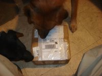
Naturally it had to be inspected upon arrival, but since the chief inspector is no longer available, two of the journeymen stepped in.
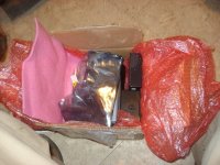
Little trouble getting the pics, as the inspectors don't yet know when to step out of the way:
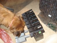
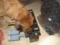
All but two are Dell laptop packs, 7 of tthem identical, plus two similar ones, then an IBM laptop pack and another very different unit. Probably not all the cells are good, but there's almost 1KWh of raw packs, based on the labelling their manufacturers gave them, not including this one:
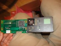
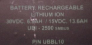
It is a dual-voltage pack, meaning that it has two sets of cells in it, configurable for either series or parallel configuration by design. 30V 6.8Ah one way, 15V 13.6Ah the other. I am *sure* I have seen these packs here on ES before, that someone was experimenting with them or something very like them, but can't find it now.
It appears to be made to be water-resistant, perhaps waterproof, though I don't intend to test that. :lol: It'll be nice if I don't have to open this one up. IIRC he said it was from a military VoIP unit of some type, and hasn't seen much use yet. Weighs about 3lbs.
The 6-pin round connector that mates with the provided PCB's connector has power and ground separate for each cell set, plus another pin I don't know what it is yet, and second ground for one of the cell sets.
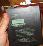
It also has little LCD displays, 5-segment, to show if the separate cell sets are at 0 - 100% charge. They're at 80% or so according to the displays, but I haven't checked the output with a meter yet.
It ought to make a good lighting pack for one of the bikes, in the 15V 13.6Ah mode. Current limit's not on the label anywhere, so I went googling, and found a couple of data sheets from the manufacturer:
http://ultralifecorporation.com/download/89/
http://ultralifecorporation.com/download/218/
The datasheets are a bit different from the case markings, but it basically shows typical usage would have 7.2Ah in 30V mode at 0.5A continuous at 23C, or 14.4Ah in 15V mode at 1A.
Max limits are 6A continuous or 18A for 5 seconds in 30V mode, and 12A continuous or 36A for 5 seconds in 15V mode. That should be more than enough for even my automotive incandescent lighting setups, or halogen bulbs, etc. It even has a resettable fuse that activates at 70C, and resets at 55C, htough a one-time fuse goes at 91C. :lol: Has overcurrent protection at 19A, dunno what it does when that's exceeded though.
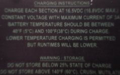
Says recommended charge rate is 3A to max voltage of 16.8V, hold till current drops to 300mA, and max rate is 4.8A. Presumably this is for 15V mode, both cell sets paralleled.
Ah...found another page with all that above in copyable format:
http://ultralifecorporation.com/commsys/products/military-batteries/ubbl10-ubi-2590-smbus/
More batteries for this build showed up today; an unexpected donation, from GMUseless:

Naturally it had to be inspected upon arrival, but since the chief inspector is no longer available,

Little trouble getting the pics, as the inspectors don't yet know when to step out of the way:


All but two are Dell laptop packs, 7 of tthem identical, plus two similar ones, then an IBM laptop pack and another very different unit. Probably not all the cells are good, but there's almost 1KWh of raw packs, based on the labelling their manufacturers gave them, not including this one:

It is a dual-voltage pack, meaning that it has two sets of cells in it, configurable for either series or parallel configuration by design. 30V 6.8Ah one way, 15V 13.6Ah the other. I am *sure* I have seen these packs here on ES before, that someone was experimenting with them or something very like them, but can't find it now.
It appears to be made to be water-resistant, perhaps waterproof, though I don't intend to test that. :lol: It'll be nice if I don't have to open this one up. IIRC he said it was from a military VoIP unit of some type, and hasn't seen much use yet. Weighs about 3lbs.
The 6-pin round connector that mates with the provided PCB's connector has power and ground separate for each cell set, plus another pin I don't know what it is yet, and second ground for one of the cell sets.

It also has little LCD displays, 5-segment, to show if the separate cell sets are at 0 - 100% charge. They're at 80% or so according to the displays, but I haven't checked the output with a meter yet.
It ought to make a good lighting pack for one of the bikes, in the 15V 13.6Ah mode. Current limit's not on the label anywhere, so I went googling, and found a couple of data sheets from the manufacturer:
http://ultralifecorporation.com/download/89/
http://ultralifecorporation.com/download/218/
The datasheets are a bit different from the case markings, but it basically shows typical usage would have 7.2Ah in 30V mode at 0.5A continuous at 23C, or 14.4Ah in 15V mode at 1A.
Max limits are 6A continuous or 18A for 5 seconds in 30V mode, and 12A continuous or 36A for 5 seconds in 15V mode. That should be more than enough for even my automotive incandescent lighting setups, or halogen bulbs, etc. It even has a resettable fuse that activates at 70C, and resets at 55C, htough a one-time fuse goes at 91C. :lol: Has overcurrent protection at 19A, dunno what it does when that's exceeded though.
Says recommended charge rate is 3A to max voltage of 16.8V, hold till current drops to 300mA, and max rate is 4.8A. Presumably this is for 15V mode, both cell sets paralleled.
Ah...found another page with all that above in copyable format:
http://ultralifecorporation.com/commsys/products/military-batteries/ubbl10-ubi-2590-smbus/
Voltage Range
30V Mode: 24.0 to 33.6V
15V Mode: 12.0 to 16.8V
Average Voltage
30V Mode 28.8V
15V Mode 14.4V
Capacity
30V Mode: 7.2Ah @0.5A @ 23°C
15V Mode: 14.4Ah @ 1.0A @ 23°C
Max. Discharge
30V Mode: 6.0A continuous
15V Mode: 12.0A continuous
Max. Pulse Discharge
30V Mode: 18.0A for 5 seconds
15V Mode: 36.0A for 5 seconds
Energy
207Wh
Energy Density
144Wh/kg, 230Wh/l
Weight
1440g
Cycle Life
> 300 cycles @ C/5 to 80% of initial capacity @
100% depth of discharge
Operating Temperature
-32°C to 60°C
Self-Discharge
< 5% per month
Communication
SMBus v1.1 communication protocol
SBD v1.0 data set support
Protection
Over Voltage Limit: 4.30V (per cell)
Under Voltage Limit: 2.40V (per cell)
Over Current Protection: 19.0A
Re-setatable Fuse: Activates @ 70°±5°C
RE-sets @ 55°±5°C
One-Time Thermal Fuse: Activates @ 91°±4°C
Charging
Recommended charge rate is 3.0A to max voltage of 16.8V in a temperature range of 0°C to 45°C. Hold at 16.8V until current declines to 300mA. max charge rate is 4.8A.
BikeFanatic
1 kW
Good find.
How are you going to charge these packs? Use the venom charger that you fixed.
What kind of power supply does the venom take? ( I may have an extra power supply so you do not have to use SLA , then charge the SLA, too many steps.
How are you going to charge these packs? Use the venom charger that you fixed.
What kind of power supply does the venom take? ( I may have an extra power supply so you do not have to use SLA , then charge the SLA, too many steps.
Oh, I have a high-current power supply I could use to run the Venom, it's just that I can only use it in the utility room (because it has to plug into the dryer's 220V outlet), which currently I can't get the bike anywhere near, forcing me to take the pack off the bike to charge it. It's easier to charge the SLA and then use it to run the Venom.ianmcnally2 said:Good find.
How are you going to charge these packs? Use the venom charger that you fixed.
What kind of power supply does the venom take? ( I may have an extra power supply so you do not have to use SLA , then charge the SLA, too many steps.
It's the same power supply I'll use to charge the LiCo with once I complete the pack(s) from it:
http://www.endless-sphere.com/forums/viewtopic.php?p=283087#p283087
The Venom takes 11V to 18VDC in; not sure what the max current draw it could pull from the supply is--haven't tried to measure that yet. (didn't think of it).
I have two broken supplies that will work with it, if I can fix them (the one tha tcame with it, and one from GCinDC)
If I could find an old electric stove with a cord still on it that matched the one in my kitchen, I'd leave the DCS55-55 SOrenson in the kitchen next to the stove, and I'd probably be able to run charging wires from it to the bike in the living room easily enough.
I considered adding a second 220V outlet on the other side of the wall from the kitchen stove outlet, in parallel with it, but I haven't found one that I can mount in the wall in such a way that I can remove it and plaster over the hole when I someday move out. (I doubt that anyone else would want a 220V outlet in their living room).
It would be better to instead extend the conduit and wiring for the dryer's 220V outlet from the utility room into the back family room, simply moving that outlet in there until I someday move out, and then put it back the way it was. (I don't use the clothes dryer at all, as it costs way too much and even when it's not hot here, it's dry enough to dry clothes on a line outside, even at night).
999zip999
100 TW
Tell them is for a heater outlet and that's that. Your tell them is for a exercise bike doctor orders.
Oh, I don't have to make any excuses for any changes I make here, as long as they are 'improvements' to the place. But it isnt' really safe to have an 220V outlet within potential child's reach, as it would be where I would have to put it.
So I would rather remove it when I leave (if I do; I'd rather not but lack of money may not leave me the choice).
So I would rather remove it when I leave (if I do; I'd rather not but lack of money may not leave me the choice).
while my left hand heals up, i've been working on stuff that doesnt' require much strength/etc. dug up this project thread and started again on that ultralife pack, after i ran across it when looking for zeners for farfle.
since i want to test it out as a lighting pack for crazybike2, i borrowed just the connector on the big pcb and put an anderson-ended cable on it so it connects the two internal packs in parallel, for 15vdc at 13.6ah.
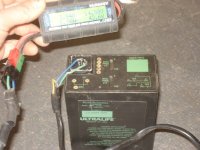
i hooked it up to the lighting system, and it sags enough at the moderate currents (less than 0.5c) that i don't think i'd wanna use it for a motor system pack. wattmeter screenshots below.
first is with max lights on (left turn signal, highbeam headlight, brakelight).

then with just lts and hbh.

then with just hbh,

then with just lowbeam

then with nothing on to see rest voltage.

pack was at 80% soc to start with, according to it's little gauge, and 60% when i was done, assuming there's 5 blocks in the display.
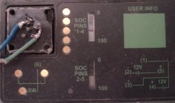
noew i'm charging it up on the big sorenson (the little ones are in use on another battery) at 2a, 2/3 of the max allowed charge current, at 16.5v, the recommended charging voltage.
the soc meters on top don't go up even when the voltage across teh pack increases during charge, so they must be a charge-counter rather than a voltmeter, from an internal bms of some type. makes me wanna open it up but i promised myself i'll leave it as-is until it has a problem because it is sealed and should be more useful that way, espeically if i ever decide to try it out as a light-use motor pack just strapped to a "normal" bike.

since i want to test it out as a lighting pack for crazybike2, i borrowed just the connector on the big pcb and put an anderson-ended cable on it so it connects the two internal packs in parallel, for 15vdc at 13.6ah.

i hooked it up to the lighting system, and it sags enough at the moderate currents (less than 0.5c) that i don't think i'd wanna use it for a motor system pack. wattmeter screenshots below.
first is with max lights on (left turn signal, highbeam headlight, brakelight).

then with just lts and hbh.

then with just hbh,

then with just lowbeam

then with nothing on to see rest voltage.

pack was at 80% soc to start with, according to it's little gauge, and 60% when i was done, assuming there's 5 blocks in the display.

noew i'm charging it up on the big sorenson (the little ones are in use on another battery) at 2a, 2/3 of the max allowed charge current, at 16.5v, the recommended charging voltage.

the soc meters on top don't go up even when the voltage across teh pack increases during charge, so they must be a charge-counter rather than a voltmeter, from an internal bms of some type. makes me wanna open it up but i promised myself i'll leave it as-is until it has a problem
final charge data was
16.43v
15.08vm
45.2wp
2.88ap
6.181ah
99.1wh
now all 5 segments of the soc lcds are 'lit'. i am guessing that since it does not specify a time for charging, it self-balances internally by discharging any uneven cells, and that the soc meters would probably show the loss of capacity if it was enough after balancing. :? at that point i guess i'd just leave it on the charger for several hours to see what happens.
anyway, it's chargd up and for the next few days i wll use it as the lighting pack on crazybike2 in place of the other one i'd been using.
used about 0.64ah on the way to work, and about 0.78ah on the way home. not recharging it yet, as i want to test if it has a working internal lvc to protect itself.
i suppose i could just let it sit and run overnight for that rather than being caught on the road without lights, but i still ahve the regular lighting pack on the bike if i need it. i'd rather do the discharge test under actual load conditions with intermittent use of brake light and turn signals, but constant use of lowbeam headlight and very occasional use of highbeam.
i suppose i could just let it sit and run overnight for that rather than being caught on the road without lights, but i still ahve the regular lighting pack on the bike if i need it. i'd rather do the discharge test under actual load conditions with intermittent use of brake light and turn signals, but constant use of lowbeam headlight and very occasional use of highbeam.
dnmun
1 PW
AW, the ping signalab BMS is built for the lifepo4 cells. it balances them to 3.65V and are not useful for balancing the lico cells you have which need to get to 4.12V.
if you decide to build a lifepo4 pack and use the ping signalab BMS for that and need parts for the BMS, then i have some spares here for parts.
if you decide to build a lifepo4 pack and use the ping signalab BMS for that and need parts for the BMS, then i have some spares here for parts.
Similar threads
- Replies
- 5
- Views
- 859
- Replies
- 2
- Views
- 341

