RFID power switch - (techie stuff!)

Jeremy Harris

100 MW
Joined
Oct 23, 2007
Messages
4,208
Location
Salisbury, UK
One thing has bugged me with each of the ebikes I've built, the clunky way we have to turn them on and off. Up until now my daily use ebike has had a key switch, that turns the pre-charge and controller on, and a plug in power link that connects the main power. The turn on procedure is to turn the key switch on, wait a second or two for the capacitors to charge and then plug the link in. The process is reversed to turn the ebike off. It works well, with no big sparks or surges due to the capacitors charging too fast, but is clunky, all the same. My car doesn't have a key, it just senses when the fob is in my pocket and lets me start by pressing a button, so I thought it'd be nice to have something similar for the ebike.

What I came up with is a combined slow turn on switch and coded lock, using an RFID tag (Radio Frequency Identification). The tags are unique and coded with a ten digit number, so are pretty secure (more secure than a key switch, for sure). The readers are now pretty cheap, too, so all that was needed was a bit of electronics to take the code from the reader, check that it is the correct one for the bike and then turn on the power to the controller, with a slow switch on speed to limit the inrush current.

The circuit diagram and code below shows how I did it. The RFID reader is a cheap unit from China (http://www.seeedstudio.com/depot/125khz-rfid-module-uart-p-171.html) that outputs a serial data stream whenever it senses a tag. This gets fed to a small microcontroller that reads the code, checks it against a stored code for the bike and if it matches then turns on some FETs to turn the controller on. The FETs are deliberately turned on slowly, via a resistor and big capacitor, to limit the inrush current. My bike already has a handlebar mounted controller cut off switch, so I used this as a combined "arm" switch and cut off switch. When the switch is turned on the power switch gives a very short beep once a second to let you know the power is on but that the controller isn't yet powered up. Waving the RFID tag within an inch of the antenna coil reads the tag and turns the power on, with the power switch giving a 1 second long beep as confirmation. The controller will then stay latched on until the handlebar cut off switch is turned off, when it turns off and needs to read the tag again to turn on. On my bike the battery "fuel gauge" gives me a good indication that power is on, so I haven't fitted a power on LED, but one would be a good idea normally.

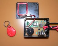
First a photo of the prototype unit:
Bike power switch photo.jpg

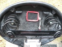
I built the prototype into a small plastic box about 2 3/4" x 2" x 1". The second version has been built into a new controller box on the bike, with the antenna glued under the bike saddle:
Antenna under saddle.JPG

This is a bit stealthier, as it's out of sight and you can turn the bike on by just waving the red tag under the saddle, making it possible to more easily turn the power on when on the move.

Here's the circuit diagram, which should be fairly self explanatory. The microcontroller is similar to the one I used for the "fuel gauge", a cheap, easily programmed (with free software) Picaxe 08M2:


and finally here's the code to make it work, with a dummy ten digit tag number:

Code:
;Electric bike RFID power switch


;The code below loops around giving a short beep every second until a valid key is detected, when it then turns the power on,
;beeps for one second and the programme ends, leaving the power switch FETs turned on.

;The code restarts at next power on via a handlebar mounted cut-off switch that also supplies the power to the unit.
;With the handlebar switch off the FET power switch is also off.

;The first byte sent by the RFID reader is always 02h, and is ignored in the code below
;The next ten bytes are the RFID tag code in ASCII, read into bytes b1 to b10
;The read value is compared with the tag code obtained from the serial terminal during set up
;after ten ASCII data bytes the unit sends two bytes of checksum and a single byte for end of transmission, 03h, also ignored in this code


#picaxe 08M2

setfreq m8		;Needs to run at 8MHz in order to get 9600 baud for RFID reader output


main:
		
	serin [2000,no_valid_code],c.4,T9600_8,b0,b1,b2,b3,b4,b5,b6,b7,b8,b9,b10,b11,b12,b13 ;read RFID tag number into variables b1 to b13
	
	IF b1="0" AND b2="1" AND b3="0" AND b4="0" AND b5="0" AND b6="5" AND b7="3" AND b8="5" AND b9="3" AND b10="B" THEN ;Dummy tag number - get real tag number from testing with serial terminal using code below that's commented out
	HIGH c.2	;turn on beeper
	HIGH c.1	;turn on FET switch
	PAUSE 2000
	LOW c.2	;turn off beeper
	ELSE
	LOW c.1	;keep FET switch turned off when no valid tag
	LOW c.2	;keep beeper turned off when no valid tag
	PAUSE 2000
	GOTO no_valid_code
	ENDIF
	END		;comment this out during set up so that the code loops continuously to read tag ID numbers
	
no_valid_code:

	HIGH c.2	;turn on beeper
	PAUSE 20	;keep beeper on for 10 mS
	LOW c.2	;turn beeper off


	;Uncomment the code below to read tag ID numbers via the serial port and terminal when setting the unit up for a new tag ID
	
	;setfreq m4 ;slow picaxe back down for serial comms to work at 4800 baud (not needed when line below commented out)
	
	;sertxd (#b0,",",b1,",",b2,",",b3,",",b4,",",b5,",",b6,",",b7,",",b8,",",b9,",",b10,",",#b11,",",#b12,",",#b13,cr,lf)
	
	;setfreq m8	;speed clock back up again to run at 9600 baud for RFID reader
	
		
	GOTO main	;loop back to main programme if tag read isn't valid or if no tag detected

Maybe someone might be geeky enough to want a "keyless entry" ebike....................

Jeremy
 
That is way cool Jeremy. As usual you are ahead of the pack! My programming skills are dormant and I gotta build a battery, but perhaps after I will give this a try.
otherDoc
 
Thanks for the kind words. It's easy enough to build, Doc, and the bits are reasonably cheap. The microcontroller is available in the US from these folk: http://www.sparkfun.com/search/results?term=Picaxe&what=products for $2.95.

The programming software is free and can be downloaded from here: http://www.picaxe.com/Software/PICAXE/PICAXE-Programming-Editor/

The only other thing needed is a serial download cable, either the $27 one from Sparkfun, or an Infineon controller type USB/serial adapter (which may or may not be OK - it depends on the exact make of chip in the cable).

These little microcontrollers are a great way to get into playing with this stuff, as they are really easy to use, being designed primarily for the education market. There's also a good support forum (which is a bit UK-centric) here: http://www.picaxeforum.co.uk/forumdisplay.php?2-Active-PICAXE-Forum

Jeremy
 
Very slick. I'm making one of these. Thank you so much for doing the work and sharing the code and schematic so anyone can easily implement it Jeremy. :)
 
liveforphysics said:
Very slick. I'm making one of these. Thank you so much for doing the work and sharing the code and schematic so anyone can easily implement it Jeremy. :)

Glad you like it, Luke. I reckon it would be a neat way of powering up pretty much any EV. The only things to watch are the voltage range (the 1k2 resistor in the power feed is OK for up to around 45V to 50 V, but needs increasing in value for higher voltages), and the current rating. I used 4 off 4110's because I had a bunch of them spare, and they are OK for around 50 A or so without heat sinks. You might want to add a few more in parallel if you want to handle loads more current.


texaspyro said:
Implant an RFID chip in your ass and all you have to do is sit on the saddle... :twisted:

Might work, but you'd need to sort of "bear down" hard to get it within range of the antenna..... :lol:
 
This is awesome. I have been thinking of something like this and you have already done all the hard work - Thanks! :mrgreen:

Would it be possible to read two different tags, one for full power and one to hand to inquisitive members of the local law enforcement that restricts the power to the legal levels? I was either going to control this by my cycle analyst or go directly into my 12FET from Lyen and grounding the terminal to give me speed one on the three speed switch settings.
 
Sir Knight returns to the Round Table from his long absence & adventuring away from our castle-es only to return with the one of a kind story that only he can tell so markedly "wicked sick" aka Badass Cool. 8)

Well, you're most welcome "home" Sir Harris... may the feasting & merriment begin... with an electric start! :p :twisted:
 
Planky said:
This is awesome. I have been thinking of something like this and you have already done all the hard work - Thanks! :mrgreen:

Would it be possible to read two different tags, one for full power and one to hand to inquisitive members of the local law enforcement that restricts the power to the legal levels? I was either going to control this by my cycle analyst or go directly into my 12FET from Lyen and grounding the terminal to give me speed one on the three speed switch settings.

There's plenty of spare code space, so there's no problem in adding another tag number to check. The code would need a bit of a rewrite, but I can post something up later that should do the job. The pins on the microcontroller would need swapping about a bit to drive another output (use pin C.3 for the serial input from the RFID and use c.4 to drive a transistor switch). The transistor switch could then switch to one of the limited speed settings on something like an Infineon/Xiechang controller, effectively giving a "legal" low power set up with the swipe of a tag.

deVries said:
Sir Knight returns to the Round Table from his long absence & adventuring away from our castle-es only to return with the one of a kind story that only he can tell so markedly "wicked sick" aka Badass Cool. 8)

Well, you're most welcome "home" Sir Harris... may the feasting & merriment begin... with an electric start! :p :twisted:

Thanks for the kind welcome back. Glad you like it.

Jeremy
 
For my application, I've all ready got a monster 1kA contactor and a pre-charge circuit built into the Sevcon. I just like the RFID replacing the enable switch. :)
 
This is sooo cool. I'm totally interested in learning how to do this and implement. Thank you so much for sharing your genius!

Maybe I can bury an RFID tag in my car's key fob and have it be dual purpose!
 
liveforphysics said:
For my application, I've all ready got a monster 1kA contactor and a pre-charge circuit built into the Sevcon. I just like the RFID replacing the enable switch. :)

Dead easy, Luke, just use a single FET to switch the contactor coil and remove the 1uF capacitor I added to the gate to slug the rise time down. Should work a treat as it stands then, with just a diode across the contactor coil to take out the switch off spike.

cal3thousand said:
This is sooo cool. I'm totally interested in learning how to do this and implement. Thank you so much for sharing your genius!

Maybe I can bury an RFID tag in my car's key fob and have it be dual purpose!

Glad you like it. The tags are available in loads of different forms, from credit card size, through the key ring one I've used to sterile implantable ones you could have injected under your skin.................. Any 125 KHz EM4100 compatible tag should work OK. The key rings ones are around $0.50 each, not sure of the price for some of the other shapes of tag.
 
Jeremy Harris said:
texaspyro said:
Implant an RFID chip in your ass and all you have to do is sit on the saddle... :twisted:

Might work, but you'd need to sort of "bear down" hard to get it within range of the antenna..... :lol:
Would work great with any suspended-mesh 'bent seat, though. ;)
 
Hal did something similar a couple years ago. I always thought about doing this and maybe even one where if my rfid gets away from the bike it goes to a slow mode. So it can be tested by the authorities to show them it only goes 32km/h lol http://endless-sphere.com/forums/viewtopic.php?f=3&t=12490&start=45
 
How about using a doggie door's guts for this? ;)
http://www.endless-sphere.com/forums/viewtopic.php?f=2&t=40251
Haven't worked out the details yet, but in theory it ought to work.
 
amberwolf said:
How about using a doggie door's guts for this? ;)

That doggie tag has a battery in it. The best RFID systems use a passive sensor. The transmitter sends a pulse out to a coil/antenna in the tag, that charges a cap, the cap powers the tag enough for it to send its data payload. That is how the implantable ones work. Hmmm, a little midnight grave robbing at the pet cemetery might yield a few tags to play with. Reuse, repurpose, reccyle, and all that, you know :twisted:
 
Uh, huh. ;) I can see it now--I go to the vet's with one of my dogs, and while they are checking the chip in some other dog, the one in my back pocket sets their thing off and it comes up with the original dog's information, and they think Fido has come home! :lol: :roll: (I know it wouldnt' work like that...)


The only reason for me wanting to use the doggie-door sensor/tag is that I was able to snag one for cheaper than the parts to build a "real" RFID (and I can use the rest of the door, too). One benefit of the battery in the tag is that you get a longer range if you want it, without a bigger antenna. Downside is that the battery will eventually die and leave you unable to start the bike, unless you regularly test and/or replace it.
 
amberwolf said:
Downside is that the battery will eventually die and leave you unable to start the bike, unless you regularly test and/or replace it.

Backup is a methane sensor in the seat. You have to fart the proper pattern to start it... reminds me of the old "North Atlantic Squadron" ditty... "Carter the Farter would start 'er..."
 
Jeremy,

It looks like the BJTs you have there are obsolete and getting harder to find. What characteristics should I make sure of before finding a suitable substitute besides being an PNP polarity?


Is there a best Linear regulator to use as well?

thanks,
 
Sorry for the late reply, I missed this post.

Any suitably rated small signal PNP and NPN transistors will do, as they aren't switching fast or handling more than a few mA. The voltage regulator I used was the small LM78L05, pretty much an industry standard part available from several vendors.

The limits on my unit are not more than 50 V, because of the rating on the transistors, the rating of the voltage regulator and the values of the resistor chain that turns the FETs on. If you want to use a higher voltage than this then some values will need to be changed.
 
Finally getting around to trying this amazing mod that you provided. But I wanted to make sure I have the right components since I will be building at least 2 of these units for my bikes. The first one will be run on 12S2P LiCo/RC Lipo, so I believe all the components can remain with the specs that you have laid out.

But my second bike will be running 24S2P, so I believe the components will need higher power ratings and possibly spec changes? (I'm hoping that just ratings need to be upped)


I read fechter's about a 12V zener diode between the gate resistor and the FETs, but don't fully understand the concept behind it. Sounds like it will allow me to put a larger resistor in place of the 22k gate and run up to 100V.

Any info you could provide would be appreciated.
 
Great that you're going to give this a go. The changes needed for a 24S LiPo (~100V max) are these:

1. Change the 1k2 resistor that feeds the voltage regulator to a 3k9 resistor, 2W rating.

2. Change the BC 212 PNP transistor for a 2N5401

3. Change the BC182 NPN transistor to a 2N5551

4. Change the 22k resistor that goes from the collector of the PNP transistor to the FET gates to a 62k resistor (1/4W is fine). No real need for the 12V zener, as just increasing the value of the resistor keeps the FET gate voltage within safe limits.

The 4110's will *just* about be OK on 24S, but are right on the limit. You could go for 4115's, but I'd suggest using 6 of them to be on the safe side, as they have a higher on resistance.

Good luck!
 
Jeremy Harris said:
Great that you're going to give this a go. The changes needed for a 24S LiPo (~100V max) are these:

1. Change the 1k2 resistor that feeds the voltage regulator to a 3k9 resistor, 2W rating.

2. Change the BC 212 PNP transistor for a 2N5401

3. Change the BC182 NPN transistor to a 2N5551

4. Change the 22k resistor that goes from the collector of the PNP transistor to the FET gates to a 62k resistor (1/4W is fine). No real need for the 12V zener, as just increasing the value of the resistor keeps the FET gate voltage within safe limits.

The 4110's will *just* about be OK on 24S, but are right on the limit. You could go for 4115's, but I'd suggest using 6 of them to be on the safe side, as they have a higher on resistance.

Good luck!

Thanks for the information and the good luck wishes. I already have a bunch of 4110's, so I will use those. If they go pop, I will upgrade the circuit to (6) 4115's.

Working on this project, I found I'm definitely more used to writing code than creating hardware. I've already modified your sample code to allow 3 different keys to be used for my wife, my self and an emergency key. I'll post the code and my results after I get everything working and tested.

I actually bought a bunch of extra parts suitable for a lower voltage setup to save on shipping and I plan on populating a few boards to have available for trade bait :mrgreen:
 
Sounds good. I like the idea of "trade bait"!

I'm with you on the code thing, I find it a pain to have to make the hardware just to get a bit of code to do something useful............
 
Back
Top