A123 AMP20M1HD-A Battery pack kit

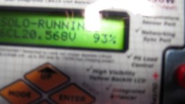
Well this Hyperion charger is giving me fits, and it may not work correctly. I found 2 bad connections in my balance harnass but I cannot get the Hyperion to start a charge cycle for Lifle battery. It asks me for the number of cells and shows 5 so I change it to 6 cells and it refuses to charge even without the balance connector. I can't believe it! The battery voltage is 19,6 which is 3.22 for each of 6 cells so it ought to work. Very frustrating. Sorry to rant here but I may have to give it back or get a new one that works. It previously charged a 12 volt tractor battery fine.I'm using a 15 volt 24 amp power supply
otherDoc
 
Rather than disassemble the battery I am going to run the balance wires directly from one bolt in each block. For the second six cell pack I may try to solder or wire the traces first but I may also directly wire the balance connectors directly from the blocks too. The traces seem to be a weak link, and even the cell log wont respond to them. I will make some circular solder connections on the wires ends to go through the frontmost bolts on each block anf that will insure a solid connection. Now if I could only figure out why my Hyperion won't bulk charge the battery!
otherDoc
 
Started my 24s build today. Got tired waiting for my evassemble BMS they somehow messed up my order and let it set 10 days so who knows.

Taking some pics. No issues so far all the comments here really helped a lot. Biggest lessons learned id say is cover up all connections with tape.

did that from the get go and no sparks as of yet.

6 down 18 more to go may take a few days as I don't want to rush we will see.
 
Ill get some pic's up when it's worthy just had to start over after having about 7 cells connected.

Made a new discovery regarding full tabs. when doing something large like a 24s battery if you stick with the full tab
length there is a lot of play in tab below the board which could easily result in a short. You could easily place something
between the cells to stop this , but having the tabs flex that close to each other would still concern me.

I left the tabs at 12mm rather then 8 cutting off about 7mm from the top. Ill update how it works out going to finish my
tab adjustment tonight and start the actual build again tomorrow.

I bought the same punch from amazon in this thread for the holes and it works great. I used a plastic speedway card as
a template just lining it up to the corner of each tab and punchin thru the holes already made.
 
ohzee said:
You could easily place something between the cells to stop this , but having the tabs flex that close to each other would still concern me.

Why not use clear wrapping tape to seal & strengthen lower tabs (both sides) hanging below pcb & use (foam/weather strip or ?) spacers if necessary?
 
docnjoj said:
Well this Hyperion charger is giving me fits, and it may not work correctly. I found 2 bad connections in my balance harnass but I cannot get the Hyperion to start a charge cycle for Lifle battery. It asks me for the number of cells and shows 5 so I change it to 6 cells and it refuses to charge even without the balance connector. I can't believe it! The battery voltage is 19,6 which is 3.22 for each of 6 cells so it ought to work. Very frustrating. Sorry to rant here but I may have to give it back or get a new one that works. It previously charged a 12 volt tractor battery fine.I'm using a 15 volt 24 amp power supply
otherDoc

To me it sounds like a wrong wiring problem. I am not familiar with hyperion charger but if you set correct settings might be wrong wire order. Double check that, i had problem like this with BMS not letting charge the batt. because of balance wiring. But if it does not charge without balance wires connectors might be your charger. 3.22 is a bit low for lifepo4 as resting voltage for these cells are 3.3v and full charge at 3.65. I Have my iCharger for 100usd and it charged my newly assembled 6S pack beautifully balancing to 3.65 each cell.
I was designing the kit around trimming the tabs and it might be OK, end blocks tricky thou as it is tight fit for cover plate at 10mm. Still dont see the point on leaving longer tabs, serves no purpose. I would suggest on making one tab with holes, checking it if it is spot on and making template for others to save time. What i did i have marked center line where the holes must be, then coming 5mm from sides and 22.5mm from ether side for center hole then drilling.
 
deVries said:
docnjoj said:
The traces seem to be a weak link, and even the cell log wont respond to them.

Arn't the traces the main power lanes of voltage transfer for this design? :? You're not supposed to transfer power through the blocks, right?

The traces are NOT a weak link and they are meant for balancing which does not require high current. Basically balance charger or BMS drains the cell to keep them at the same level and that it does on low current. Blocks are for clamping tabs except 10mm end ones. These are for main power to charge or drain your batt. Even if you decide to use 4mm blocks for higher current, would be good as they touch directly with the tabs.
 
But if it does not charge without balance wires connectors might be your charger. 3.22 is a bit low for lifepo4 as resting voltage for these cells are 3.3v and full charge at 3.65. I
That is what I am concerned about. It simply refuses to charge and says "bad connection" even with just the two power connectors and no balance wires being used. The DVM reads 19.6 volts for the pack.
otherDoc
 
docnjoj said:
But if it does not charge without balance wires connectors might be your charger. 3.22 is a bit low for lifepo4 as resting voltage for these cells are 3.3v and full charge at 3.65. I
That is what I am concerned about. It simply refuses to charge and says "bad connection" even with just the two power connectors and no balance wires being used. The DVM reads 19.6 volts for the pack.
otherDoc
What is your charger model so i could look it up on the net?

There is few options to charge on mine, there is charge, balance charge. If i would try charging on balance charge without balance leads i would get connection error, so check that. Then regarding your voltage i'm pretty sure you can set your top voltage at 3.65 on your charger?! Check battery chemistry and set it to LiFe.
 
Okey Dokey folks. The charger works, at least on 1S. I managed to lower the charge rate to about 7 amps and set it for 3.60. This is a new cell. It looks like I am going to have to charge each cell individually through the blocks. Luckily I have 2 single cell Voltphreaks 3.65 chargers at about 2 amps each. This is gonna be a long day. Then I will track down and fix the balance leads. I may have damaged more than one of them, which is why Cell logs wont read! At least we are working, if only in baby steps. I still would much rather use agniusms kit than any other means to build this battery! For the second battery I will cover the traces first before the start and check continuity before the start of the second build! Better safe than sorry!
otherDoc
 
W
hat is your charger model so i could look it up on the net?

There is few options to charge on mine, there is charge, balance charge. If i would try charging on balance charge without balance leads i would get connection error, so check that. Then regarding your voltage i'm pretty sure you can set your top voltage at 3.65 on your charger?! Check battery chemistry and set it to LiFe.endless-sphere.com/forums/viewtopic.php?f=35&t=35394

It is the Hyperion 1410 and the power supply is about 13 volts and 20 amps or so.
There is one possibility that I haven't tried yet and that is to drop the amps to 3-4 and retry charging the whole battery. At least some of my scientific method training is useful!
otherDoc
 
I'm double posting this also to the Hyperion 1420 thread also since it involves mostly the charger.

Well waddaya know! It must have coughed up its hairball and is now bulk charging the 6S battery! I have it set real conservatively at 3.55 volts per cell and 90 % fof that so it should be safe! I also dropped the amps to 3.5 down from 7. Once it charges to that level (prolly to 3.5 volts I will remove the safety cover and try to attach a new ballancer directly to the blocks. I really do not want to take the battery apart again so this will be completely visible just in case I make a mistake with the balance order. Since I am the one who screwed up the traces I have to use this workaround. The second battery will be much improved and I will check each trace twice for continuity. If I am not sure of a connection I will run the balance wire(s) directly from the blocks. This second build should go much more smoothly since I have already done one successfully (mostly)
otherDoc
 
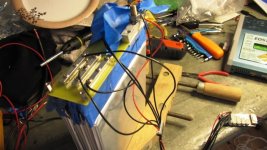
Well I got it to work! Yahoo! A bit unconventional and definitely not as neat as agniusm's design but it works. Charges and balances. Now to figure out how to make this a bit neater and protected.IMG_0372.JPGIMG_0371.JPG
otherDoc
And I pwned that Hyperion!(Ithink that is the hipster term) I'm definitely not a hipster.
 
Doc I preassemble on the table and get set, but don't flip the cells till install and draw the + and - on the cells. Only assemble once as taking it apart is where problems happen for me. And clean all that shortable junk away and over head. I remenber one guy triing to fix a battery with two boxes of nails open and hanging half out of the box over his work table. i told him don't touch or move the boxes till done. Freakie looking Pic. Not one box of nails but two with easy access as the nails where falling out. Sometime we make are owm problems. Good luck.
 
999zip999 said:
Doc I preassemble on the table and get set, but don't flip the cells till install and draw the + and - on the cells. Only assemble once as taking it apart is where problems happen for me. And clean all that shortable junk away and over head. I remenber one guy triing to fix a battery with two boxes of nails open and hanging half out of the box over his work table. i told him don't touch or move the boxes till done. Freakie looking Pic. Not one box of nails but two with easy access as the nails where falling out. Sometime we make are owm problems. Good luck.
Believe me I'm not going to disassemble anything! Way too much work. I just have to figure how to attach the wires and get them out of the way and then I can start on pack 2, which I will be MUCH more careful with.
otherDoc
 
Believe me I'm not going to disassemble anything! Way too much work. I just have to figure how to attach the wires and get them out of the way and then I can start on pack 2, which I will be MUCH more careful with.

Are you going to use the pcb designed balance connectors on your second build? Still use full tabs too?

It must have coughed up its hairball and is now bulk charging the 6S battery! I have it set real conservatively at 3.55 volts per cell and 90 % fof that so it should be safe! I also dropped the amps to 3.5 down from 7.

Do you have any idea what went wrong before? It would be nice to know if you figured-out what the problem was/is, so we don't make the same mistake & have to get a random guess solution. ;)
 
My guess is that inner block fell lose and shorted the trace. One rule assembling - be extra careful, don't rush. As i stated before i have build my kit for the first time myself on that vid. It was in a hurry and i had some sparks but then again i haven't used any tape or precautions. I don't know how else i can help as i have not expected people having such difficulties assembling this..
Any way, any questions ask, before doing, not do then regret not asking!
 
agniusm said:
My guess is that inner block fell lose and shorted the trace. One rule assembling - be extra careful, don't rush. As i stated before i have build my kit for the first time myself on that vid. It was in a hurry and i had some sparks but then again i haven't used any tape or precautions. I don't know how else i can help as i have not expected people having such difficulties assembling this..
Any way, any questions ask, before doing, not do then regret not asking!

Only docnjoj has had issues. Ohzee has not reported any problems yet. I will be building my 16s two batteries in about 10-14 days once I receive the A123 cells.

Questions:

1) Are there separate traces on the PCB for the main power to run through in series vs balance charging traces?

2) How many amps can the balance traces handle?

3) I would like to see a video of you doing/making the balance wiring.

Also, when do you plan to do more amp-load tests on video?

Thanks. :D
 
Yea the kit is very well designed. As we all know anything with power is dangerous especially if shorted.

I think you have done a most excellent job agniusm and also have an excellent product. I should have some pics
to share later tonight just taking it slow which I feel is good advice.
 
Questions:

1) Are there separate traces on the PCB for the main power to run through in series vs balance charging traces?

2) How many amps can the balance traces handle?

3) I would like to see a video of you doing/making the balance wiring.

Also, when do you plan to do more amp-load tests on video?

1. No. The main power in series runs through the cells giving you desired voltage. End cell tabs - positive and negative is your main power source for charging and discharging the battery.
2. Balance traces are rated at 3amps.
3. I will do the video on that and load test - cell behavior soon, lots going on here at the moment, just need an opportunity.

I don't want to get in to detail on how balance charging is done, there should be plenty of info on the forums but in short:
those balance traces are for BMS or balance charger like Hyperion or iCharger. The way it works is your BMS or charger measures voltage between first cell - to +, than from 1st cell + to 2nd cell - than from 2nd cell - to 3rd cell + and so on. If BMS or charger sees that one cell is at 3.65V and the rest say at 3.4V, it stops the charge process and it drains high cell trough resistor or other way till it is same as other cells and reengages charging process. It does that till all the cells are at 3.65V. Same happens for discharge using BMS. BMS disconnects draw from the cells if one reaches 2.0V. So to further answer your question those traces and connector with pins are for monitoring and low amp drainage of cells only. Some folks here and on DIY car do not use balance charge all time. They balance cells once before assembling the pack. They dont use BMS or balance charger hoping that the cells will be in balance. In this case you don't use the balance connector at all although i don't recommend that!!!
 
I do want to balance charge these cells using isolated single cell chargers. These are rated at 2amps each. If traces are rated at 3amps, then there should be no problems with resistance or heat buildup charging at 2amps through each of the 16 balance traces for 16s = 32amps @ 3.65v, correct? :?:

Thanks for all your help & answers. I too think you have a very good design. :D
 
deVries said:
I do want to balance charge these cells using isolated single cell chargers. These are rated at 2amps each. If traces are rated at 3amps, then there should be no problems with resistance or heat buildup charging at 2amps through each of the 16 balance traces for 16s = 32amps @ 3.65v, correct? :?:

Thanks for all your help & answers. I too think you have a very good design. :D
You are on your own here. its meant for balancing only, if you charge separate cells through balance connector it is a risk you have to take.
 
Back
Top