Cyclebutt
100 W
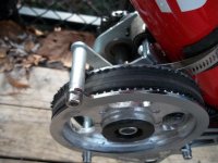
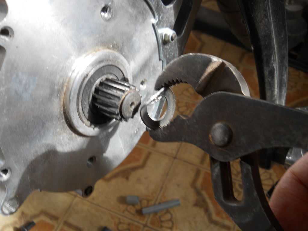
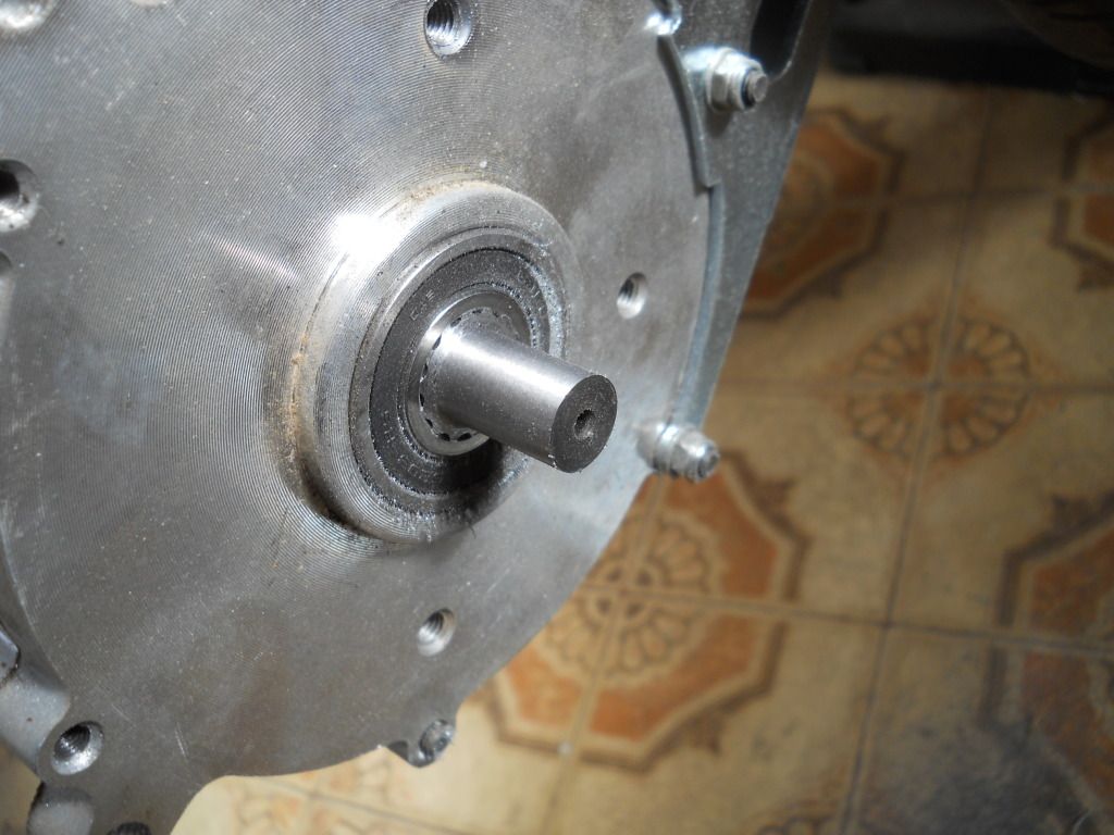
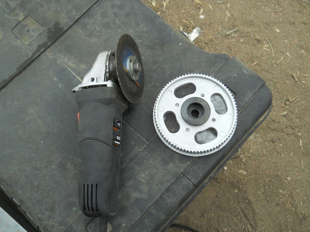
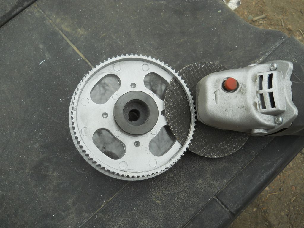
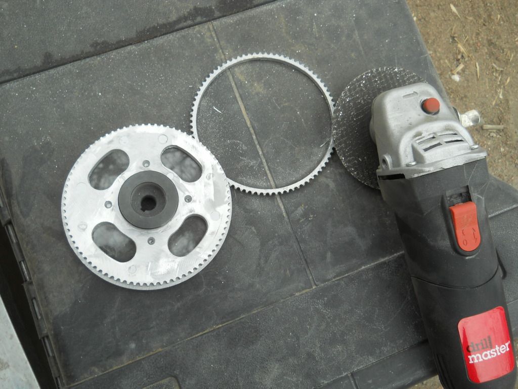
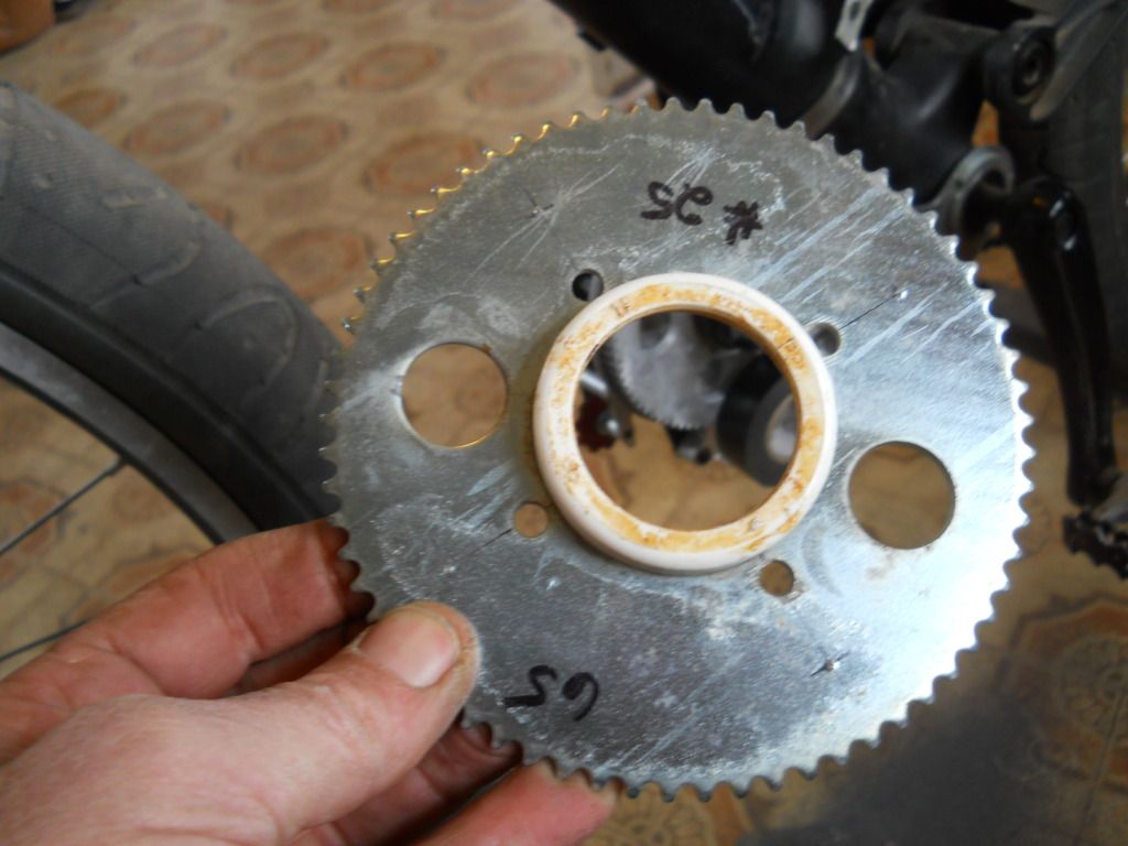
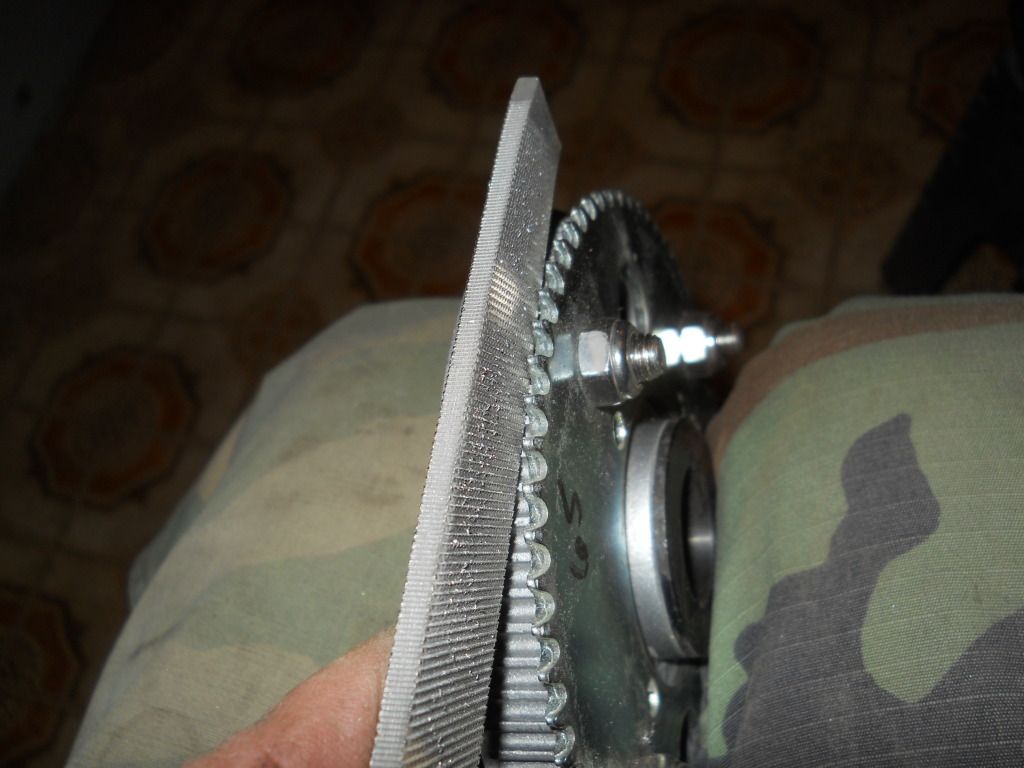
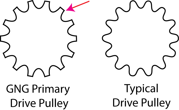
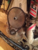
I'm definitely "IN" with the adjustable sheets. However, I have a gut feeling that part of the reason the GNG primary has that "deep plunge" idler, is for teeth engagement. I seem to remember someone installed a smaller belt (same width) on the stock kit. This resulted in stripped teeth, thought to be caused by less engagement (or lack of an idler?). Anyone remember this, gotta link?
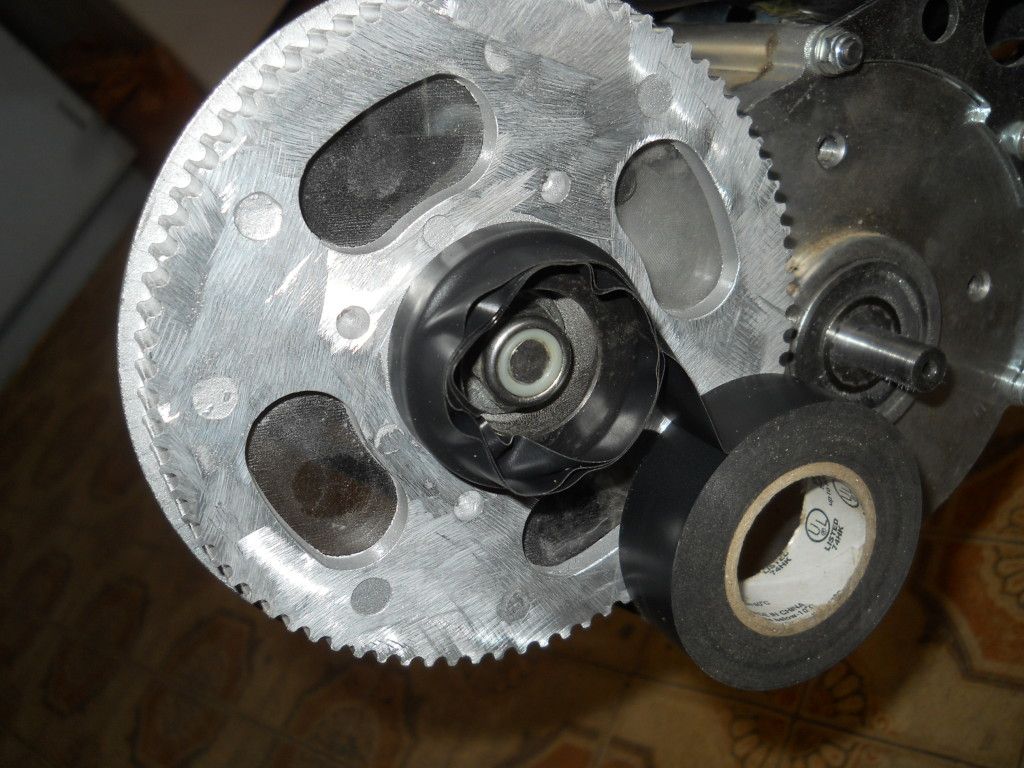
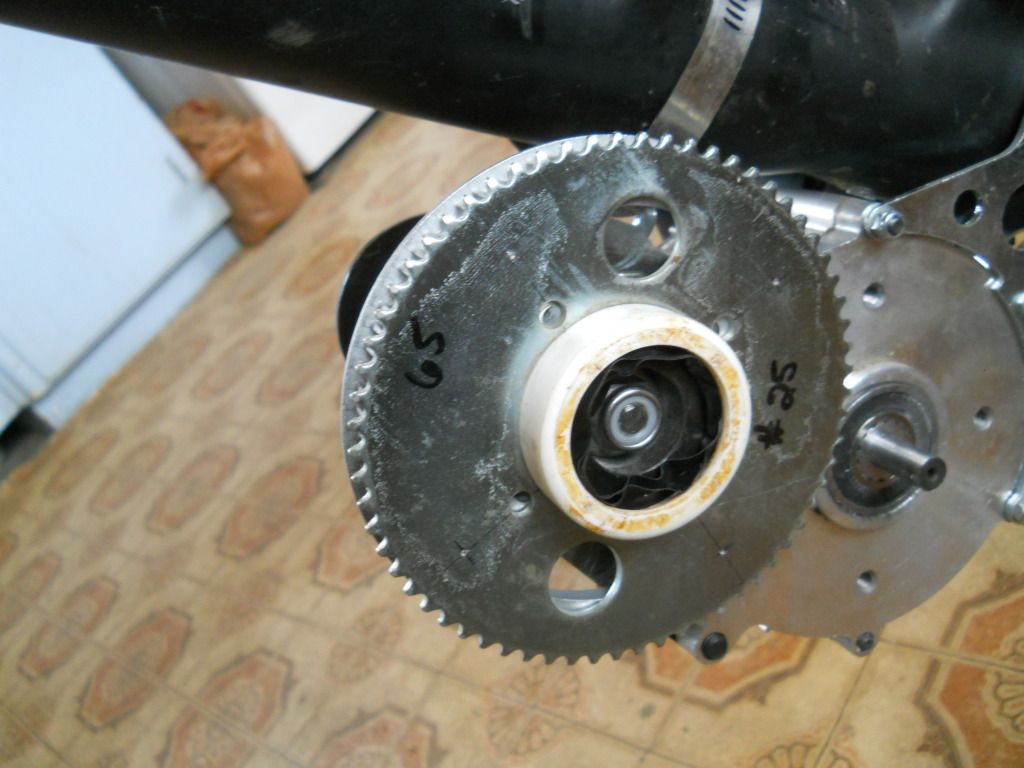
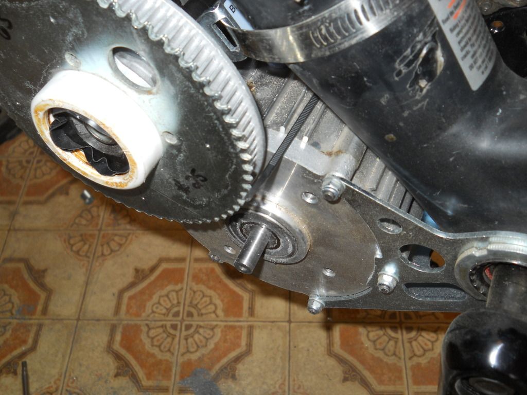
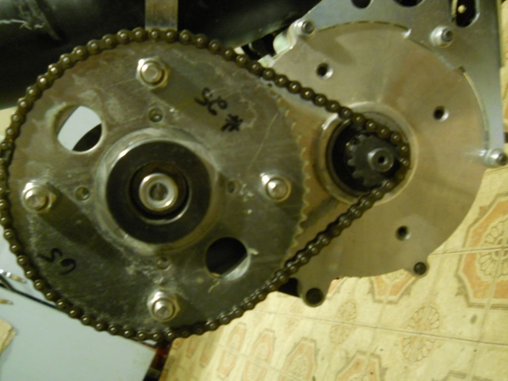
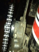
Anyhow, I see these sheets as the best "first step" because it allows us to be rid of that crazy stock idler, the likes of which I have never seen before. If I end up with a chain drive later, the adjustable sheets should make adaptation that much easier, anyway.
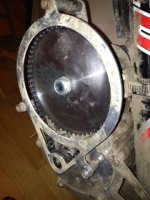
Edit: Oops! Just realized that the sharp edged (thanks, LightningRods) drive pulley could be the "teeth stripper" of the smaller belt conversion, hmm...
Anyhow, I see these sheets as the best "first step" because it allows us to be rid of that crazy stock idler, the likes of which I have never seen before. If I end up with a chain drive later, the adjustable sheets should make adaptation that much easier, anyway.
Edit: Oops! Just realized that the sharp edged (thanks, LightningRods) drive pulley could be the "teeth stripper" of the smaller belt conversion, hmm...


![ATTACH]](/sphere/proxy.php?image=http%3A%2F%2F%5BATTACH+type%3D%22full%22+alt%3D%22100_2034%2520%282%29.jpg%22%5D0%5B%2FATTACH%5D&hash=e99904a9e84bac52566805261874c27c)