RFID Keyswitch

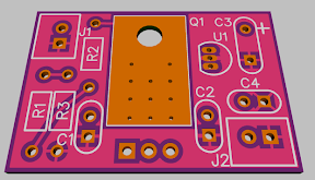
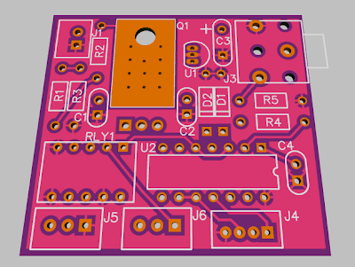
Okay, the internet dropped out here for a few minutes in the midst of submitting the board, but it appears to be in now.

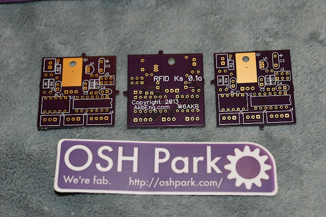
So in 10 days or so I'll have three bare boards. I have a Mouser order started with several of the parts that I don't already have. It will also require a DigiKey order as Mouser doesn't carry the JST-XH bits and I don't think I have the 4 pin units. On the final board it would be good to use the Grove connector if I can find that.

The next step is to buy parts, test and program one. This is a bit harder than the earlier projects in that programming of the chip is required. So anyone who wants to try testing this board will have to be up for that. Not sure there will be any volunteers. :roll:

I wrote some code for this awhile back, but it is not tested either, other than passing compiler checks, and the pinout is different on this setup as well as a few other changes.

So I'll probably have to test this one myself, which means it is competing with a bunch of other projects. This should be easier than the Battery Monitor which has fine pitch soldering along with more programming complexity. I need to get my hot air soldering station tuned up before I tackle that one. So this one may be able to go first.

So how can we make this available to ES members?

A bare board isn't much good for most folks as the programming equipment is required. A few have that gear and could do that, but not most.

A mini-kit is probably the minimum practical setup - a bare board, a pre-programmed micro, and several key fobs that are already programmed in.

Partially assembled mini-kit - micro is soldered on the board, programmed, and key fobs provided.

Full kit - programmed micro and all parts except the RFID receiver.

Complete kit - Full kit plus RFID receiver.

Assembled and tested, with or without the RFID receiver.

And so on.

An additional complexity is the voltage ranges of the pre-regulator need to be determined and change both the FET and the resistors that set the ratio. So there is not just one set of fixed parts, it can vary depending on what you want it to cover voltage wise.

Not sure which way to go. If this project depends too much on my time, it may stall. If someone else wants to build and sell them, we might make an arrangement.

I would tend to start with a mini-kit and see how that goes. Might be able to ramp up to more later, though the demand may not be there.
 
Found some Grove connectors on Amazon. They have 2mm spacing, so a bit smaller than JST-XH. A little bending should work for the prototype, or cut the connector off a Grove cable and change it to JST-XH, or solder the wires to the PCB. I can change it for the final board, though there are various RFID receivers that can be used with this board, not just Grove type, so choosing the connector is somewhat arbitrary.

Note that the pinout I used for the JST-XH is not the same as the Grove pinout. I will fix that on later boards, and change to a Grove socket, but these first three boards will be different. Probably easiest to just cut a grove cable and solder the wires to the board in the right place.
 
I see the Grove connectors are available on Seeedstudio, and they have a crimper for them as well. They also have the female cables pre-made. Also found in searching was mention that the Grove connectors are available at Digikey as JST but no part number was given. They said to search for 2mm (pin spacing) rectangular connectors.
 
I had another thought. Since this board is relatively simple, and to make it easier for folks to program themselves, perhaps a Picaxe chip version would be interesting. So I did some research and found a 14M2 will almost fit in the same spot. I had to make quite a few minor changes, and enlarge the board, but this is what it would look like. I also figured out the Grove connector size and pinout and changed that. The Picaxe uses a 3.5mm phone jack for programming, that is on the board, as are the resistors it needs for serial programming input. These items required the board be enlarged to 1.6 by 1.8 inches or so.

RFID%2520Keyswitch%2520px%25200.1.png


Now are there any Picaxe folks out there who would like to tackle assembling, testing and programming this board? It requires a Grove 125 khz RFID receiver and tags available from Seeedstudio for under $20 (plus shipping), plus less than $20 worth of parts including the 14M2 processor, and a Picaxe programmer and the ability to debug hardware and program Picaxe. I would provide a PC board, schematic and support info.

Any volunteers?

I don't think I'll make any of these Picaxe boards unless someone wants to tackle the programming. :)
 
I stripped out the regulation section onto a separate small board - dual stage, low quiescent current, up to 140 VDC 50 mA short term (at 100V in that's 5W of heat). 5V out. The board is 1.3 by 0.9 inches or 1.2 square inches. Might be a handy building block. The quiescent current should be well under 1mA, and the board should be able to dissipate about 2 watts of heat. :

hv%2520lqi%25202s%2520vreg.png


I'll probably make some of these after the circuit is tested out on the RFID prototypes.
 
RFID Reader Measurements

Today I powered up the two board-level RFID readers that I have. One is an "Electronic Brick" unit and the other is a "Grove" model, both 125 khz type.

Conditions: 4.9V power supply indicated on its own LCD readout, using precision Fluke DVM for current, coil on a wood desk surface.

Electronic Brick Unit

26mA Idle
28mA Peak Reading Tag
22mA Tag Close

Grove Unit

28mA Idle
30mA Peak Reading Tag
23mA Tag Close

Detection range was 1-2" on both, a good distance from the coil.
Both units have LEDs, one for "on" and one for "reading"

The Electronic Brick units are discontinued - no longer available, the Grove units are available. They are very similar, though the Grove unit is slightly smaller and their connectors differ though the pinout is the same. Electronic Brick to Grove adapter cables are available.
Both units were purchased from Seeedstudio about a year ago in 2012.
Both consist of a small PC board and a plug-in separate coil. They weigh very little but need protection from physical abuse and moisture.
Both are specified to work on 5 volts at 50 mA. The adjustable supply I used didn't want to put out exactly 5.0V.

This is well within the current available from the low quiescent current 50mA TO92 second stage regulator on the board. :)

Since both the AVR and PIC recommend no more than 20mA per pin the plan is to use a pair of output pins in parallel to provide power to the RFID Reader. This is important since we don't want to power it all the time. But doing this requires careful attention to detail when writing the software. If one pin is set high while the other pin is set low then the power supply to ground path through the two output driver pins will flow lots of current. So it is necessary to either switch both pins simultaneously, or to set them to float (or input mode) and then set each to high. Turning off set them back to float or input, and then to low.

During the time the RFID is active the supply current will be about 30mA for the receiver plus whatever the micro requires, perhaps another 5mA. Most of this heat will be developed in the first stage regulator, depending on how the resistors are programmed. On a 100V ebike this will be about 3.5 watts which is too much for long term heating, but short term should be no problem. I don't think we need to leave the RFID on for more than about 10 to 30 seconds after the Run switch comes on and powers it up, giving plenty of time to swipe the RFID tag (before timing out, shutting down the RFID Reader and configuring for very low current. :)
 
There are two modes for these RFID Receivers, Serial/UART and Wiegand26. There is a small jumper to select between U and W. Some receivers have only one mode, make sure you get the appropriate unit, or that it is settable. The unit Jeremy used appears to be Serial only.

The Picaxe is probably not fast enough to do Wiegand26, so Serial 9600 baud can be used for that. On the AVR the Wiegand26 is perhaps better since it does not require calibrating the baud rate clock for serial.

I just checked with my scope and the Grove Serial pinout is:

1 Yellow Serial / W1
2 White W0
3 Red +5V
4 Black 0V Ground

I adjusted the PC board for the Picaxe such that hserin is connected to Grove 1 so the serial can read the RFID Receiver, since the Picaxe can only do that on the one pin.

I'll sort out the Wiegand26 pins later, the AVR is faster and more flexible and they can be sorted out in software. Update - looks like the Electronic Brick documentation is a bit more detailed than the Grove board, and since we know the pinout of the adapter cable we can infer the Wiegand26 arrangement for the Grove. This will be verified when we test the board.

Docs:

E_Brick http://www.seeedstudio.com/wiki/index.php?title=Electronic_brick_-_125Khz_RFID_Card_Reader
Grove: http://www.seeedstudio.com/wiki/Grove_-_125KHz_RFID_Reader
Wiegand26 http://www.robotshop.com/media/files/pdf/wiegand-protocol-format-pr25.pdf
 
Looks to me like Jeremy's sample code for his 8M2 Picaxe can be modified to work on the 14M2 - the serin command can read the RFID as serial. There will be additional code needed to handle powering up and down the RFID and pulsing the relay, then going to power down mode. Not too hard. Might be nice to convert the hexcodes to real tag numbers so people don't have trouble figuring out what value to put into the program, and to allow several tags to be used as valid keys.

Here is Jeremy's example, linked earlier in this thread:

http://www.endless-sphere.com/forums/viewtopic.php?f=2&t=39589

More good examples from Picaxe Forum, search for Picaxe RFID:

http://www.picaxeforum.co.uk/archive/index.php/t-18886.html

Nice Tutorial Here:

http://www.picaxeforum.co.uk/archive/index.php/t-21989.html
 
This is an interesting project, and I completely agree that a locked cutoff switch is mandatory on any ebike, but RFID sure seems like a lot of complexity. There are much simpler more reliable approaches to the issue.

This is a keyed lock from McMaster-Carr, inset into the bar-end. It cuts power to the CA, thus disabling the bike. I plan to make up a plastic key-head to change the profile to a rounded "button" that will cover the bar-end, and won't be vulnerable to breaking off.
 

Attachments

  • keyed.jpg
    keyed.jpg
    20.1 KB · Views: 2,936
Is using RFID overcomplicated?
Could you use a magnetic switch and a magnet, or reed switch instead? Or a 4mm plug and socket with the 4mm plug completing the switch circuit?
 
I keep coming back to this subject too. I'm tempted by the thought of an rfid device, but being realisticly it's probably a bit much with too little of an advantage over a key switch. The ideal would be some kind of proximity sensor, something that gets sensed when I get near the bike without having to swipe a token over a detector but is carried on a keyring in my pocket.
Maybe a fingerprint sensor?
 
OT from the original project, but in reply to Alsmith:

That's one way to do it, or you can even use RFID equipment off other existing items to DIY this sort of thing.

For instance, there are doggie doors that use some form of RFID with the keytag on the doggie collar--but they're usually really expensive. I have one I got super cheap on clearance, which AFAIK survived the fire, but it'll be at least a few months before I can dig aorund and see if it survived the looters to try my hand on the project, using it's electronics that normally turn a little motor for a moment to unlock and relock the doggie door flap, to instead lock and unlock the bike. I mentioned it in at least one or two thread around here other than my own CB2 thread, whenever the RFID keyswitch idea has come up in the last year or so, but with more detail.

I'd *really* like it to not only electrically "lock" it, but also to physically engage a steering and/or wheel lock, though I'm not entirely certain about tha tpart since if there were a failure of the RFID detection in some wya during a ride it would lockup the wheel and/or steering *while in motion*....so it'd need some sort of physical interlock that prevents it from locking as long as the wheels are in motion. No idea how ot do that yet--I could easily do it electriclaly, pulse counting the speed sensor off a wheel, but mechanically/physically, I dunno.

Anyway, enough OT rambling.
 
amberwolf said:
...
I'd *really* like it to not only electrically "lock" it, but also to physically engage a steering and/or wheel lock, though I'm not entirely certain about tha tpart since if there were a failure of the RFID detection in some wya during a ride it would lockup the wheel and/or steering *while in motion*....so it'd need some sort of physical interlock that prevents it from locking as long as the wheels are in motion. No idea how ot do that yet--I could easily do it electriclaly, pulse counting the speed sensor off a wheel, but mechanically/physically, I dunno.

Anyway, enough OT rambling.

My thoughts on this was not a physical lock but locking the wheel electrically using the phase wires. My Lyen controller already has the wheel lock built in (just connect one wire) but it means the controller is left switched on while locked this way, so the CA stays lit up.
 
You can "lock" the wheel electrically simply by shorting hte phase wires--but you must first disconnect htem from the controller or smoke it if it's powered on (esp with any throttle given). And you must make ABSOLUTELY sure that it's IMPOSSIBLE for the "lock" to ever engage during riding, especially with a front wheel. ;)

That kind of thing has been discussed a fair bit around ES before, and it comes down to using more expensive (and at least sometimes bulkier) switches or relays that are designed to be "unbounceable", so their contacts can

A) never break contact for the phases when in operation
B) never make contact between phases when in operation

You *don't* want to ever just go grab some random relay or set of relays and try using those for the purpose, as regardless of their voltage/current ratings, if they're not made that way then the contacts can and probably will bounce off and on--two things can and probably will happen:

A) If current/voltage is sufficient at the instant of bounce, the contacts will arc and probably weld together, meaning the phases won't *dis*connect from the controller when you change over to "lock" mode, and thus can (probably will) damage or destroy the controller.

B) If bounce is severe enough, the contacts could flip all the way over to "lock" mode and short the phases, creating an extremely powerful brake...and in the process will probably *also* do what happens in A), except now the relay is welded into "lock" mode instead (but it might still blow up the controller, and possibly damage the motor, if not all phases flipped and locked but instead arced across multiple contacts, and the controller is still trying to feed power thru the phases).

It's impossible to predict a certain result from a contact bounce, because it could range from a "glitch" in the motor operation all the way up to full phase shorting and wheel lock, and anything in between. But you don't want it to ever happen at all. ;)


You could do it electrically with FETs instead, but you would basically be building what amounts to a controller's power output stage anyway, and the appropriate control electronics...and it will also take power to operate, so at that point you might as well just use the existing built-in controller wheel lock function (which is active instead of passive, and so should be even better, anyway, as a deterrent).

So in your case I would just put a switch on the CA itself or in it's wiring harness to it, to disconnect the Vbatt wire from it. That will turn it off. You can even use a relay or FET or other transistor for the purpose, so that it turns off with your keyswitch.
 
I have a 3 position keyswitch with off / on / wheel lock. I got it as 3 way 2 pole so ignition could be on at the same time as the wheel lock. I had looked for a 3 way 3 pole keyswitch (or 4way / 4 pole) but couldn't find one. The maker is DP and I got their spec sheet which lists those as options, but nobody stocks them. I had emailed them and they said they were special order only and gave some horrendous guide price.
I started thinking about some way to use a relay or FET to handle both the wheel lock and the CA display off from one set of those contacts leaving the other for the controller ignition wire. Thinking about it now the ignition will probably be a 5V line, and I think it is 5V to the CA. I wonder if the 5V ignition line is enough to power the CA as well. Or if I could use the CA 5V input to power the ignition on. It's probably safest to ask Ed Lyen about the power they can supply.
 
Alan B said:
You can twist the wires together for a low budget approach. Confuse thieves with lots of same color wires that aren't the right ones. :)

I think you're being a bit agricultural. Here's an example on Kepler's old stealth. Also a chargeport.
Screenshot_2013-11-16-06-43-15-1.jpg

This thread is reminding me of the old story of the americans using a million dollar pen to write in space while the russians used a pencil. Sure its an urban myth, but it makes the point.
 
Back
Top