Arduino PID current limiter values

jamesv

1 mW
Joined
Jul 22, 2012
Messages
16
Location
Guernsey
Hi guys I've recent brought an Arduino to try and make a current limiter for my electric bike that uses an RC ESC. I plan on using PID to create a current limit but I am unsure of what values of kp ki and kd to use with my RC ESC, does anyone have any rough ideas?
Thanks
James
 
Please post the Arduino code that we can see what is what :)
 
The pid values will need to be tweeked for your controller as the throttle response tends to be pretty slow on a rc controller. set the controller for the fasteast throttle startup then it maybe come useable. If you are using the arduino PID library then as a starting point try P=0.1, I=2.5,D=0.

EDIT:
P increases how fast the input signal will rise ( but will also increase the over shoot ) to the set point.
I will reduce the offset between the steady state and the setpoint but to much and it can cause it to oscillate the output from one state to the other.
D is used to help slow down any rapid movements of the PIDs present value
 
Thanks guys, and gwhy I really do appreciate your help, this bike wouldn't have stood a chance otherwise! Here's my code it's probably dreadful but what do you think?
Code:
#include <PID_v1.h>

//Define Variables we'll be connecting to
double Setpoint, Input, Output;

//Define the aggressive Tuning Parameters
double aggKp=0.1, aggKi=2.5, aggKd=0;

//Specify the links and initial tuning parameters
PID myPID(&Input, &Output, &Setpoint, aggKp, aggKi, aggKd, DIRECT);

int throttleOut = 3;
int throttleIn = 5;
double throttleLevel = 0; 

void setup()
{
  pinMode(throttleOut, OUTPUT);
  pinMode(throttleIn, INPUT);
  Input = analogRead(0);
  Setpoint = 90;

  //turn the PID on
  myPID.SetMode(AUTOMATIC);
}


void loop()


{
  throttleLevel = (0.00016275*(pow((analogRead(throttleIn)),2))+102); //convert the hall throttle into a smooth pwm throttle
  
  myPID.SetTunings(aggKp, aggKi, aggKd);
     myPID.Compute();
     Output = Output;
     
  if (analogRead(0) > 100) { 
    while(throttleLevel > Output){ //if the shunt value is more than 100 run the pid until the users throttle becomes lower than the pid output
      throttleLevel = (0.00016275*(pow((analogRead(throttleIn)),2))+102);
      myPID.SetTunings(aggKp, aggKi, aggKd);
     myPID.Compute();
  analogWrite(throttleOut, Output);
     }
  }
else
{
  throttleLevel = (0.00016275*(pow((analogRead(throttleIn)),2))+102); //if the shunt value is below 100 just convert the hall throttle to pwm
analogWrite(throttleOut, throttleLevel);
}}
 
Give this a quick go and see how you get on... Im using a slightly modified library but I think it should work ok with the standard library .. only one way to find out. you can get a smooth throttle output (0-5v) by passing the pwm through a rc filter, but if you want to drive a rc controller I think you will be better using the output of the pwm to drive the input of the rc controller directly, the arduino has a servo libary ( im sure I have seen this some where ). I have not tested this code ( as I have just quickly written it ) but it is based on what I am using on my throttle interface that do work. and depending what current sensor you are using some are 2.5v output at 0A and this can throw everything out to make like it is not working...

Edit: I have just seen a error , hopefully its now sorted.

Depending on how you are going to with teh throttle output signal you may have to make some adjustments i.e if you use a hall throttle for the input then active input is around 0.8 - 4 v so you may want to do a bit of re-scaling to get full 0-5v output

Edit: oops another error in the code below ... but now fixed.


Code:
#include <PID_v1_nano.h>


/********************************************************
 * A0 (throttle input)
 * A1 (5k pot) to adjust current limit 
 * A2 (Isensor)
 * D3 (control) (throttle output) 
 ********************************************************/

//******************* Specify the links and initial tuning parameters
#define Throttle_Input_pin 0  // Throttle input A0
#define pot_Input_pin 1   //pot input A1
#define Isensor_Input_pin 2  //Isensor input A2
#define Throttle_Output_pin 3  // 0-5v output to controller D3

// ------------ PID setup -------------

double Sensor, Pid_Setting, Pid_Output;//Define the Tuning Parameters for PID
double pid_p, pid_i, pid_d;//Define the Tuning Parameters for PID
PID myPID(&Sensor, &Pid_Output,&Pid_Setting,pid_p,pid_i,pid_d, REVERSE);
// ----------------------------------------
int Throttle_v;
int pot_v;
int Current_v;
int Throttle_Output_limits;
int Throttle_Value;

void setup()
{
  //************* initialize serial communication at 9600 bits per second:
 Serial.begin(9600); 
  //************* initialize the variables we're linked to
 pinMode(Throttle_Output_pin, OUTPUT);   // sets the D3 pin as output


myPID.SetMode(AUTOMATIC);             //initialize pid
myPID.SetOutputLimits(0,254);        //set maximum output value to max throttle value
myPID.SetSampleTime(10);              //compute pid every 10 ms
myPID.SetTunings(0.1, 0.25, 0);
 
 
}
//************************************************************
//************************************************************
//************************************************************


void loop()
{

Throttle_v = analogRead(Throttle_Input_pin);
pot_v = analogRead(pot_Input_pin);  // sets the maximum allowed current limit
Current_v =analogRead(Isensor_Input_pin);

Sensor = Current_v; 
Pid_Setting = pot_v;

myPID.Compute();
Throttle_v=map(Throttle_v,0,1023,0,254)
Throttle_Value = constrain((Throttle_v - Pid_Output),0,254); // back off throttle output using pid output
analogWrite(Throttle_Output_pin, Throttle_Value); // write throttle output value to controller
}
 
I didnt notice phase current being limited at all in either sets of code. If you have battery current and a throttle signal to the esc, you have enough info to fudge a phase current calculation.
 
Hornet dave said:
I didnt notice phase current being limited at all in either sets of code. If you have battery current and a throttle signal to the esc, you have enough info to fudge a phase current calculation.

it will be measuring the battery current and backing off the throttle to a bring down the battery current to a pre-set value of current, you can use the above code to do the calculation to work out the phase current but to be honest it does basically the same thing but with more code. Or you can put current sensors into the phase leads and it will work exactly the same way but you will need a much higher reading current sensor.

the code is for basic current limiting when using a rc controller as these tend to have no current limiting at all.
 
Yep im familiar with rc esc's, having blown a few up over the years. Phase currents are an issue at high load and partial throttle. RC aircraft esc's are designed to handle their rated current only at full throttle (100% pwm duty cycle), and below full throttle, their current limits decrease at least with a linear relationship with throttle percentage (pwm duty cycle) and maybe more, i havent explored this characteristic fully. My application seems to be surviving using the above rule of thumb and plenty of extra input caps.

Just a silly example, if the esc is outputting 20% throttle (20% pwm) and you are drawing 30 amps from the battery, the peak phase amps will be 30/0.2 = 150 phase amps, aka the peak current level going thru the esc power transistors. If the esc is rated for 50 amps, 150 phase amps will likely blow it up. 50 phase amps is probably safe for a 50 amp rated esc but only destructive testing will reveal exactly what is safe and not safe.

If 50 phase amps is safe for your esc, that means the max battery current you should allow would be 2.5 amps at 5% throttle output,5 amps at 10%, 10 at 20%, etc.

Im not familiar with rc car esc's and their ratings, so take the above with a grain of salt when it comes to partial throttle current ratings for car esc's.
 
Thanks gwhy I never thought of doing it like that! I'll test it tonight when I get home. Dave I see what you're saying, that does concern me but as I have gears on the bike I'm normally at pretty much full throttle and I just vary speed with the gears mainly. First gear is about 15 mph and top speed could be up to 45 mph. I do have a fair amount of extra caps and the speed control is rated to 180A burst and I plan on limiting it to about 80A battery current. I'm hoping all of these things combined should mean the battery current limiter will be enough, I guess we'll find out!
Thanks for your help guys
James
 
Hornet dave said:
Yep im familiar with rc esc's, having blown a few up over the years. Phase currents are an issue at high load and partial throttle. RC aircraft esc's are designed to handle their rated current only at full throttle (100% pwm duty cycle), and below full throttle, their current limits decrease at least with a linear relationship with throttle percentage (pwm duty cycle) and maybe more, i havent explored this characteristic fully. My application seems to be surviving using the above rule of thumb and plenty of extra input caps.

Just a silly example, if the esc is outputting 20% throttle (20% pwm) and you are drawing 30 amps from the battery, the peak phase amps will be 30/0.2 = 150 phase amps, aka the peak current level going thru the esc power transistors. If the esc is rated for 50 amps, 150 phase amps will likely blow it up. 50 phase amps is probably safe for a 50 amp rated esc but only destructive testing will reveal exactly what is safe and not safe.

If 50 phase amps is safe for your esc, that means the max battery current you should allow would be 2.5 amps at 5% throttle output,5 amps at 10%, 10 at 20%, etc.

Im not familiar with rc car esc's and their ratings, so take the above with a grain of salt when it comes to partial throttle current ratings for car esc's.

yes you are quite right, the code that I posted will not keep the phase currents in check at partial throttle, I have only used e-bike controllers that have a phase current limiting setting so I have always relied on this to protect the controller. As it happens within the last 10mins I have been asked to do a electric conversion on a kick scooter that will use a 22v rc controller and a small outrunner ( which do not have this built in phase current limiting or any limiting for that matter ) so I will have to incorperate this into my exsiting code on my exsiting throttle interface. So looks like I will be playing with rc controllers very shortly.. :mrgreen:
 
ok I have not tested any of this so take it as it comes but Code below incorporates phase limiting along the lines of a calculation that is mentioned above.
there may have to be some tweeking to get the correct throttle back off value.


Code:
#include <PID_v1_nano.h>


/********************************************************
 * A0 (throttle input)
 * A1 (5k pot) to adjust current limit 
 * A2 (Isensor)
 * D3 (control) (throttle output) 
 ********************************************************/

//******************* Specify the links and initial tuning parameters
#define Throttle_Input_pin 0  // Throttle input A0
#define pot_Input_pin 1   //pot input A1
#define Isensor_Input_pin 2  //Isensor input A2
#define Throttle_Output_pin 3  // 0-5v output to controller D3

// ------------ PID setup -------------

double Sensor, Pid_Setting, Pid_Output;//Define the Tuning Parameters for PID
double pid_p, pid_i, pid_d;//Define the Tuning Parameters for PID
PID myPID(&Sensor, &Pid_Output,&Pid_Setting,pid_p,pid_i,pid_d, REVERSE);
// ----------------------------------------
int Throttle_v;
int pot_v;
int Current_v;
int Throttle_Output_limits;
int Throttle_Value;

void setup()
{
  //************* initialize serial communication at 9600 bits per second:
 Serial.begin(9600); 
  //************* initialize the variables we're linked to
 pinMode(Throttle_Output_pin, OUTPUT);   // sets the D3 pin as output


myPID.SetMode(AUTOMATIC);             //initialize pid
myPID.SetOutputLimits(0,254);        //set maximum output value to max throttle value
myPID.SetSampleTime(10);              //compute pid every 10 ms
myPID.SetTunings(0.1, 0.25, 0);
 
 
}
//************************************************************
//************************************************************
//************************************************************


void loop()
{

Throttle_v = analogRead(Throttle_Input_pin);
pot_v = analogRead(pot_Input_pin);  // sets the maximum allowed current limit
Current_v =analogRead(Isensor_Input_pin);

Sensor = Current_v /(1023/10000* Throttle_v/100); 

Pid_Setting = pot_v; // now sets phase current limit ?

myPID.Compute();
Throttle_v=map(Throttle_v,0,1023,0,254);
Throttle_Value = constrain((Throttle_v - Pid_Output),0,254); // back off throttle output using pid output
analogWrite(Throttle_Output_pin, Throttle_Value); // write throttle output value to controller
}
[/quote]
 
If im reading things right, your pid routine compares Sensor vs PID_Setting and the result is used to reduce the throttle as needed. It would have taken me 3x the lines of code to do the same thing but my senility is a different topic.

I think you are going to want to control BOTH battery current and phase current. I would suggest something like this:

Sensor = Current V (like the earlier code which you posted)

PID_Setting = minimum (Pot_V or (max phase current * throttleoutput %)) (excuse my lack of proper syntax, i havent coded any arduino code lately)

So in this example, the pot would limit battery current. The second term simply computes the maximum allowable current which is limited by phase current. You would have to define the max phase current as you please (hard code the value, use another pot, etc..), and its important thatyou use the throttle output to the esc from the previous loop, converted to percentage. I.e., if the rider has full throttle set, but this controller has the esc set at 30%, we need the 30% value to calculate the maximum allowable current as limited by phase current, not the 100% that the twistgrip is set to.

Also... The motor will never start with the pseudo code for PID setting, as you start with 0% throttle, and the second term for pid setting would be zero. So, somehow the minimum PID setting has to be limited to no lower than some value that allows the motor to start.

Piece of cake.
 
I agree that the battery current will also need limiting as you suggest, but I havent really thought about the best way of doing it.
as this code stands the battery limit will be the same as the phase limit.

initiallaly with no output to the motor there will be no current, sensor value will be 0 so throttle output will be unchanged.

like i have said I have not run this on a processor so it may need some adjustments, but the principles are all there.

if you have code that works as well as the pid library with less overhead then please post it here.

edit : Just read through the above code again and yes the 0% throttle will cause the program to have a error. so another line of code is needed to just make sure this error don't occur.

Code:
if (Throttle_v <=0) Throttle_v=1;
Sensor = Current_v /(1023/10000* Throttle_v/100);
 
i have been having a think :shock: , and I think the most elegant way to incorporate battery limiting as well would be to use two pid controllers ( maybe even a third to smooth everthing out ) you can then just sum the pid outputs and take the total away from the throttle value. This will have to be tested in real life as by using 2 or more pids it may introduce a fair bit of delay and cause to much oscillation around the setpoints
 
Two pid routines would also work fine im sure. However, you would not sum the outputs, but rather use the most restrictive of the two.

If you plot the phase current limited current and maximum battery current against throttle output to esc, you would find that below a certain throttle %, phase current is always limiting, and above a certain throttle %, the battery current is the limit. The crossover point would be:

Throttle output crossover = battery current limit / phase current limit

Also, dont use the throttle input from the twist grip throttle for phase current calculations, instead, use the throttle output to the esc as that is representative of the pwm duty cycle of the current going from the esc to the motor.
 
I have included a servo output bit of code .. I have not test this code so it may or may not work.

edit:
The servo library used in this is a additional download library from the arduino playground ( thought it was a standard library ).
also the servo needs to be driven from a anolog output not a digital output .. :oops:

edit:
just changed code to use the standard servo library.


Code:
#include <PID_v1_nano.h>
#include <Servo.h> 

//******   use this for servo control
Servo myservo;  // create servo object to control a servo 

/********************************************************
 * A0 (throttle input)
 * A1 (5k pot) to adjust current limit 
 * A2 (Isensor)
 * D3 (control) (throttle output)   
 ********************************************************/

//******************* Specify the links and initial tuning parameters
#define Throttle_Input_pin 0  // Throttle input A0
#define pot_Input_pin 1   //pot input A1
#define Isensor_Input_pin 2  //Isensor input A2
#define Throttle_Output_pin 3  // 0-5v output to controller D3

// ------------ PID setup -------------
double Sensor, Pid_Setting, Pid_Output;//Define the Tuning Parameters for PID
double pid_p, pid_i, pid_d;//Define the Tuning Parameters for PID
PID myPID(&Sensor, &Pid_Output,&Pid_Setting,pid_p,pid_i,pid_d, REVERSE);
// ----------------------------------------
int Throttle_v;
int pot_v;
int Current_v;
int Throttle_Output_limits;
int Throttle_Value;

void setup()
{
  //************* initialize serial communication at 9600 bits per second:
 Serial.begin(9600); 
  //************* initialize the variables we're linked to
 pinMode(Throttle_Output_pin, OUTPUT);   // sets the D3 pin as output

//******   use this for servo control
 myservo.attach(3);  // attaches the servo on pin 3 to the servo object 


myPID.SetMode(AUTOMATIC);             //initialize pid
myPID.SetOutputLimits(0,254);        //set maximum output value to max throttle value
myPID.SetSampleTime(10);              //compute pid every 10 ms
myPID.SetTunings(0.1, 0.25, 0);
}
//************************************************************

void loop()
{

Throttle_v = analogRead(Throttle_Input_pin);
pot_v = analogRead(pot_Input_pin);  // sets the maximum allowed current limit
Current_v =analogRead(Isensor_Input_pin);

//***** use this for battery curent limiting only
Sensor = Current_v;


//***** use this for pseudo phase current limiting
//if (Throttle_v <=0) Throttle_v=1;
//Sensor = Current_v /(1023/10000* Throttle_v/100); 

Pid_Setting = pot_v; // now sets current limit ?

myPID.Compute();
Throttle_v=map(Throttle_v,0,1023,0,254);
Throttle_Value = constrain((Throttle_v - Pid_Output),0,254); // back off throttle output using pid output

//******   use this for pwm control
analogWrite(Throttle_Output_pin, Throttle_Value); // write throttle output value to controller


//******   use this for servo control
//Throttle_Value= map(Throttle_Value, 0, 254, 0, 179);     // scale it to use it with the servo (value between 0 and 180) 
//myservo.write(Throttle_Value);                  // sets the servo position according to the scaled value
//delay(1);                           // may not be needed? and will improve response if not needed !! 

}
 
Just found this thread and it could not be a more opportune time for me. I had just a few weeks ago found the Arduino PID library with the intent of added current limits to the RC controller on my trike. The weather just turned nasty here but by Sunday I should be able to test some of this code on my trike.

I'm using the servo library and already constraining the ESC control between 60 and 120 which is servo position in degrees and the ESC is setup to recognize that as minimum and maximum input. 60 is low enough that the ESC will arm with their default setting... at least on the ones I'm using. I originally had a much broader range... but actual testing showed 60 and 120 was more than sufficient.

EDIT: your servo stuff post was not there when I started this post
 
Glad this thread is helping someone, its helping me also as I will be shortly having to do this on a kick scooter conversion.
What dave has said a few post ago about the throttle% needs to be calculated at the output is correct ,so as the code stands for the phase limiting the code will not work as expected. It will be good to get this code working and all documented as I think it would be very useful for others.
 
I just got this all patched together enough to try last night... I think its pretty close to working as it should although I didnt get a chance to test the final cut on hardware. I did have it hooked up the an RC airplane motor with a prop for a load for testing purposes as the trike is still being rewired and weather pretty nasty too.

I'm not a programmer... more of a hacker so be gentle... code could use some cleaning up.

EDIT: I've updated the code below to what I'm currently using. I did have to change it back to REVERSE

Other changes of note myPID.SetOutputLimits(5, 50); I think the controls the limits returned by PID compute which is being subtracted from the throttle speed so a large number here can make you go below the minimum speed required to keep the ESC running. I was running it some with 0 as the lower number. It appears with it set to 5 there is no correction until it is greater than 5... still need to do some more testing on that.

I added the conditional if (Sensor > 2 ) { spd = pid_spd; } and works okay with the current setting and may not be needed at all if the output lower limit is 0 and possibly even with 5. It can result in locking the speed up when experimenting with the settings.

Code:
#include <Servo.h> 
#include <LiquidCrystal.h>
#include <PID_v1.h>

LiquidCrystal lcd(7, 8, 9, 10, 11, 12);  // initialize the library with the numbers of thepins interface 
Servo myservo;  // create servo object to control a servo 
 
int pot_pin = 3;  // analog pin used to connect the potentiometer
int spd;    // variable to read the value from the analog pin 
int curr_pin = 5;  // current input pin
int curr;
int set_spd;
int anl_0;
int anl_1;
int anl_2;
int anl_3;
int anl_4;
int anl_5;
int set_screen = 5;   //input pin for screen switching 
int myscr =0;
float volts = 0;

long previousMillis = 0;
long interval = 500;


const int numReadings = 10;   //smoothing averages last 10 readings from current pin
int readings[numReadings];      // array for readings 
int index = 0;                  // the index of the current reading
int total = 0;                  // the running total
int curr_average = 0;  
int curr_average1 = 0;
int curr_average2 = 0;
float curr_average3 = 0;
int top_spd = 0;
int pid_spd = 0;
int mypid = 0;

// ------------ PID setup -------------
double Sensor, Pid_Setting, Pid_Output;         //Define the Tuning Parameters for PID
double pid_p, pid_i, pid_d;                       //Define the Tuning Parameters for PID
PID myPID(&Sensor, &Pid_Output,&Pid_Setting,pid_p,pid_i,pid_d, REVERSE);
// ----------------------------------------


void setup() 
{ 
Serial.begin(9600);
myservo.attach(3);  // attaches the servo on pin 9 to the servo object 
lcd.begin(20, 4);
pinMode(set_screen, INPUT_PULLUP);
 for (int thisReading = 0; thisReading < numReadings; thisReading++)
    readings[thisReading] = 0; 

myPID.SetMode(AUTOMATIC);             //initialize pid
myPID.SetOutputLimits(5, 50);        //set maximum output value to max throttle value
myPID.SetSampleTime(10);              //compute pid every 10 ms
myPID.SetTunings(.8, 2.5, 0);   
}
 
void loop() {

smooth();                         // calls current smoothing algorithym 
curr_average1 = curr_average - 122;         // subtract out static reading 
curr_average3 = curr_average1 / 8.00;       // scaling to show actual current

anl_4 = analogRead(4);
volts = (anl_4/34.53);

set_spd = analogRead(pot_pin);         // reads the value of the potentiometer (value between 0 and 1023) 
                                       // actual reading from hall effect throttle aproximately 200 - 800

spd = map(set_spd, 200, 800, 50, 120);     // scale it to use it with the servo (value between 60 and 120) 
                                           //200 to 800 is observed input range using hall efffect throttle


Pid_Setting = 7;           // hard coded 50 amp current lmit
Sensor = curr_average3;     
myPID.Compute();
mypid = Pid_Output;
pid_spd = (spd - Pid_Output);

if (Sensor > 2 ) { spd = pid_spd; }
  
myservo.write(spd);                                                        

anl_0 = analogRead(0);
anl_1 = analogRead(1);
anl_2 = analogRead(2);
anl_3 = analogRead(3);

anl_5 = analogRead(5);

if (digitalRead(set_screen) == 0)  myscr = myscr + 1; // switch through the output screens
if (myscr < 0) myscr = 3;
if (myscr > 3) myscr = 0;

unsigned long currentMillis = millis();            // this code gives write data without use of delay
if(currentMillis - previousMillis > interval) {     // interval coded above to 500 millis
    previousMillis = currentMillis;   

        switch (myscr) {
          case 1: write_data1();
          break;
          case 2: write_data2();
          break;
          case 3: write_data3();
          break;
          default: write_data();
 }}}

void write_data() {             // these data screens not complete... some duplicates
lcd.clear();
lcd.setCursor(0, 0);
lcd.print("Raw Input Spd ");
lcd.print(set_spd);
lcd.setCursor(0, 1);
lcd.print("Set Speed  ");
lcd.print(spd);
lcd.setCursor(0, 2);
lcd.print("Volts  ");
lcd.print(volts);
lcd.setCursor(13, 2);
lcd.print("Raw ");
lcd.print(mypid);
lcd.setCursor(0, 3);
lcd.print("Curr ");
lcd.print(curr_average3);
//lcd.setCursor(15, 3);
//lcd.print(average3);
}

void write_data1() {
lcd.clear();
lcd.setCursor(0, 0);
lcd.print("Analog 3 Input  ");
lcd.print(set_spd);
lcd.setCursor(0, 1);
lcd.print("Set Speed  ");
lcd.print(spd);
lcd.setCursor(0, 2);
lcd.print("Volts  ");
lcd.print(anl_3);
lcd.setCursor(0, 3);
lcd.print("MPH ");
lcd.print(set_spd);
lcd.setCursor(11, 3);
lcd.print("Curr ");
lcd.print(anl_0);
}

void write_data2() {
lcd.clear();
lcd.setCursor(0, 0);
lcd.print("Analog 4 Input  ");
lcd.println(set_spd);
lcd.setCursor(0, 1);
lcd.print("Set Speed  ");
lcd.println(spd);
lcd.setCursor(0, 2);
lcd.print("PID Speed  ");
lcd.println(pid_spd);
lcd.setCursor(0, 3);
lcd.print("MPH ");
lcd.print(set_spd);
lcd.setCursor(11, 3);
lcd.print("Curr ");
lcd.print(anl_0);
delay(500);
}

void write_data3() {
lcd.clear();
lcd.setCursor(0, 0);
lcd.print("Analog 4 Input  ");
lcd.print(set_spd);
lcd.setCursor(0, 1);
lcd.print("Set Speed  ");
lcd.print(spd);
lcd.setCursor(0, 2);
lcd.print("Volts  ");
lcd.print(anl_3);
lcd.setCursor(0, 3);
lcd.print("MPH ");
lcd.print(set_spd);
lcd.setCursor(11, 3);
lcd.print("Curr ");
lcd.print(anl_0);
}

void smooth()  {
    total= total - readings[index];     // subtract the last reading:    
    readings[index] = analogRead(curr_pin); // read from the sensor:  
    total= total + readings[index];    // add the reading to the total:    
    index = index + 1;     // advance to the next position in the array:                 
    if (index >= numReadings)    // if we're at the end of the array...          
    index = 0;  // ...wrap around to the beginning:                          
     curr_average = total / numReadings;  // calculate the average:       
     // send it to the computer as ASCII digits
     // Serial.println(curr_average);   
     //delay(1);        // delay in between reads for stability            
}

I did test it without the pid controlling throttle but printing the value so I could see what it was doing. I had it controlling it initially but the ESC would not arm. I had to change to DIRECT mode as it was adjusting in the wrong direction. It also needs conditional pid adjust based on throttle or current other wise it tries to drive the ESC to reach the setpoint when no throttle is input. I intend to try again this evening with those changes.
It is a home brew psycho analyst with LCD display. I've have one of the I2C interface that goes on the LCD display but I've not been able to get it to work yet.
 
all the harware have just arrived (rc motor and rc esc) so now i can also join in the fun :D ,,


@yawstick

you will need to address your i2c interface for it to work

i.e LiquidCrystal_I2C lcd(0x27,16,2); // set the LCD address to 0x27 for a 16 chars and 2 line display

I havent looked to close at your code yet, but Im suprised that you needed use direct in the pid, for my working code that I use for current limiting on my ebike controllers the pid setting is reversed.. :?
 
I've edited the code above and added some other info

EDIT: I've updated the code below to what I'm currently using. I did have to change it back to REVERSE

Other changes of note myPID.SetOutputLimits(5, 50); I think the controls the limits returned by PID compute which is being subtracted from the throttle speed so a large number here can make you go below the minimum speed required to keep the ESC running. I was running it some with 0 as the lower number. It appears with it set to 5 there is no correction until it is greater than 5... still need to do some more testing on that.

I added the conditional if (Sensor > 2 ) { spd = pid_spd; } and works okay with the current settings and may not be needed at all if the output lower limit is 0 and possibly even with 5. It can result in locking the speed up when experimenting with the settings.

It is functioning as it is posted above, it overshoots the current limit quite a bit but fairly quickly brings it down, if you have full throttle and begin reducing it there is some oscillating as it adjusts but stay close to the setpoint. The ESC I'm using is one with a custom program in it for use with quad copters... it has a much faster response to throttle changes than normal ESC's.

I think its working well enough to try it on the trike but I'm sure will take some adjusting.
 
a couple of things that you can try to speed the response up a bit is to reduce the pid sample time and you also have quite a lot of stuff going on in your code between throttle outputs maybe only update the lcd once a second may help.
 
I'm happy to report that the PID adjust worked much better on the trike than it did on the small motor on a test stand. A huge improvement in the rideability of the thing. I ending with settings very close to if not exactly what you suggested initially.

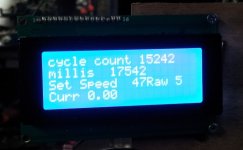
I added a cycle count and a print millis to see what kind of loop time I had.Its running just a little more than 1 millisec cycle time.

I dont have a wheel speed sensor to the arduino yet but would be interesting to have current limiting altered by speed.

psycho_analyst1.jpg
 
Finally got the I2C interface working... it seems there are quite a few different boards out there and how the interface chip connects to the LCD is not standardized. There are quite a few variations of that and the LCD libraries as well.

I found this site and it helped me get on the right track. It has quite a few different connections schemes as well as the correct library to use with the examples. In short this LCD library allows you to define which pins are connected to what in the interface.
https://bitbucket.org/fmalpartida/new-liquidcrystal/wiki/schematics#!hardware-configurations-and-initialization
 
Back
Top