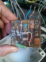
I will try both and see which is more reliable. Better than the shunt may be to use the output of the IN-AMP already on board! I am worried that it is +-8V tho 8(Stielz said:Could also get current reading through i2c on the supply, but I like the idea of a reliable external current sensor like the Allegro (and no stuffing around with calibration!)
I was going to suggest tapping into the signal from the internal shunt resistor current sensor but if you can get that get current readings through I2C thats even better, no celebration required.
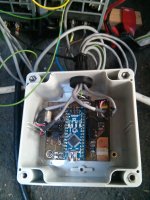
Sorry for taking so long onthis, hopefully this afternoon. Relearning embedded c and coding up some examples are taking waaaaay to long!Stielz said:I've also gone with the arduino controller for my charger, with the LCD-keypad sheild gives you alot of functionality. Coulomb counting is an important one for me so I can see how much energy I'm putting into the battery's.
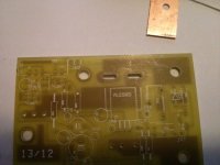
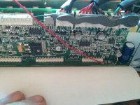
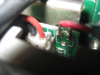
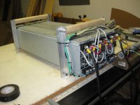
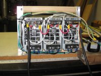
Also, I found a MUCH more convenient place to get 12V off the power section such that you do not have to remove any of the PCB's except the backplane connector (Even then you dont have to unplug the 5v). I will post a picture soon, 1000 words etc.
Keen to see this photo, I've got a side project using this PSU to power a bunch of 100W leds. Need 12V for the cooling fans
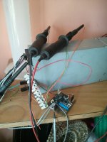
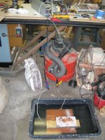
At least the Proof Of Concept with a POT and a F!ing huge reverse protection diode from an old monster UPS is working. I use the Cycle analyst as my voltage/current/Ah(coulomb counting) meter. The CA is amazing!! Pretty good using a length of the cabling as a shunt too. +-1%ish
") Here we go lets do this.
Here we go lets do this.