2 x 36V A123 with BMS but need 72V hmmmm solutions?

Spacey

100 kW
Joined
May 15, 2010
Messages
1,464
Location
United Kindom
Ok so I have 2 x spare 36v (43.8V charged) A123 11.5Ah battery packs all sealed with 12 Cell BMS attached and wired up....brilliant batteries.....

But my sensorless controller is stuck on 72V and having just sold my Greyborg and other bits including the much needed programming cable for the controllers I can not adjust the LVC on this controller.

Now I'm thinking about just connecting the two 36v batteries to make a 72V 11.5 Ah pack....problem is the BMS. Understanding that I would have to charge separately each battery...is it possible to link them up in series without having to disconnect the damn BMS each time which wil cause many problems.

Would the BMS be ok if I just hook up the two packs in series and disconnect them for charging?
 
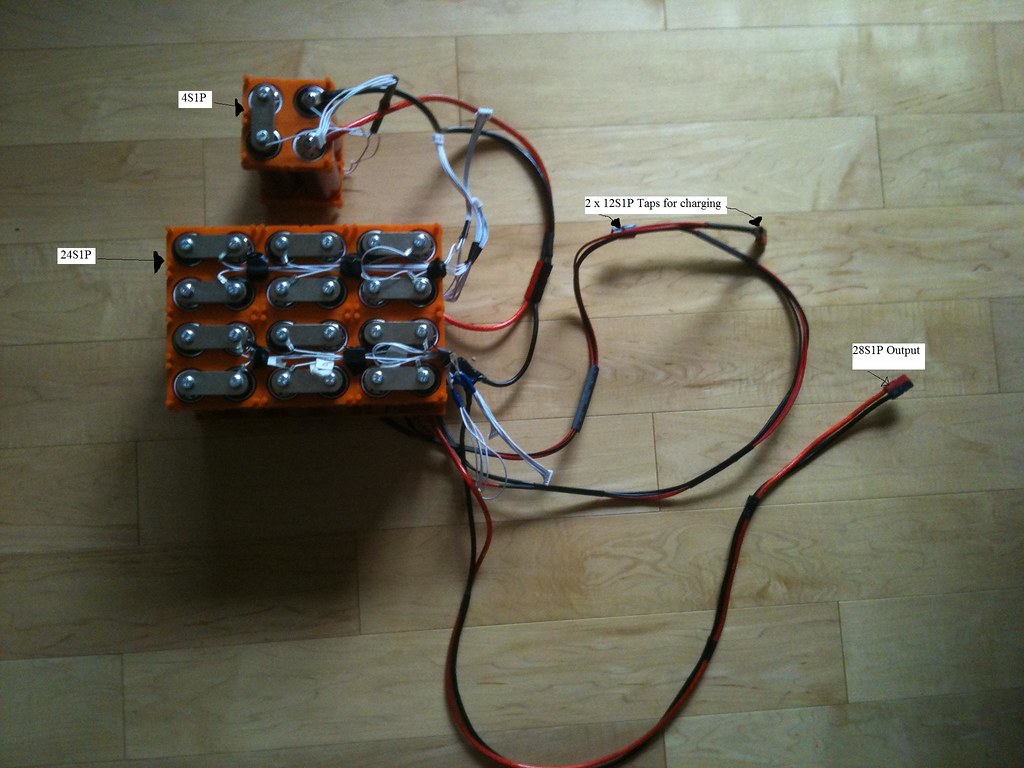
I have chosen not to use BMS's for now. I have a 28S1P 38120HP Headway. I've made 2 tap points at 12S and use 2 x 36v chargers.
then for the last 4S I use an RC charger set to 4s. It's nice to have the pack open as I can choose any cell to charge by tapping
in where ever I would like :)
I've also wired JST-hx 5pins (4s checks points) to check individual cells. Also to balance my pack, I like to attack it
at the 4S points and set my RC charger for 4S and charge 7 groups of 4S :)

Tommy L sends... \\m//

7161159852_4c26bb4740_b.jpg
 
why not use a 24S BMS instead of not using a BMS at all?

make certain the connection from one pack to the next is large gauge wire (2x10G), and connect the sense wire to this connector in the middle so the voltage drop is split between the two cells on each side of the connection.
 
I don't want to take apart these packs as I only need them for a month of commuting.

Do you think the BMS will be harmed if I series up the 2 x 36v to make a single 72v battery bearing in mind that I will charge them both separately (disconnected) on their own 36v Charger?

Tommy: Those Heasways will go way out of whack without a BMS, trust me I've been there lol. It's not so much the discharge more of the weakest cell forcing the strongest cell to make up the slack and become overcharged when you charge the pack.
 
you would not disconnect anything.

you would connect the the red wire from the positive terminal of the lower pack to the black wire from the BMS p- of the upper pack.

for the charger connections the red wire from the lower pack connection would be spliced to the hi side of the lower charger where it connects to the low side of the upper pack and the lower charger would connect the negative at C- on the lower BMS.

the high charger would connect with the red wire from the upper pack to the positive of the upper charger and the negative from that charger would connect at C- on the upper BMS. this makes more sense after editing.

assuming the chargers are isolated from ground. so each pack would charge on its on charger, and the HVC would protect it, and the LVC would shut off the connection if the BMS shuts down the mosfets.

i am sure a lot of people have done it, since i know a few here have.
 
I don't reread the whole thing, but he did say don't disconnect the sense wires before the manin wires and the packs must be of same voltage. Mybe let them rest as a pack before using.
 
dnmun said:
you would not disconnect anything.

you would connect the the red wire from the positive terminal of the lower pack to the black wire from the BMS p- of the upper pack.

for the charger connections the red wire from the lower pack connection would be spliced to the hi side of the lower charger where it connects to the low side of the upper pack and the lower charger would connect the negative at C- on the lower BMS.

the high charger would connect with the red wire from the upper pack to the positive of the upper charger and the negative from that charger would connect at C- on the upper BMS. this makes more sense after editing.

assuming the chargers are isolated from ground. so each pack would charge on its on charger, and the HVC would protect it, and the LVC would shut off the connection if the BMS shuts down the mosfets.

i am sure a lot of people have done it, since i know a few here have.

I was thinking that I would at least have to split the 2 packs when charging. I'll probably make a parallel cable for charging both batteries on 1 charger.

My main worry ...to simplify it down somewhat....was that I might do damage to one or both of the battery packs if I wire them up in series which might harm a 12 Cell 36v BMS on one or both of the packs being then the new voltage would now be 72v total from the 2 seriese'd packs?
 
999zip999 said:
Look at http://www.pingbattery.com he has a wiring diagram.


ping did not have anything similar to what he is asking. i think it will work to leave all the sense wires connected on the two packs and then chargem by making the connection for the charger on each. if the ouput of the charger is isolated from ground.
 
"I was thinking that I would at least have to split the 2 packs when charging. I'll probably make a parallel cable for charging both batteries on 1 charger.

My main worry ...to simplify it down somewhat....was that I might do damage to one or both of the battery packs if I wire them up in series which might harm a 12 Cell 36v BMS on one or both of the packs being then the new voltage would now be 72v total from the 2 seriese'd packs?"


what i tried to say was that you should connect them through the BMS negative connection of the upper pack, and the chargers would be separate except that the plus charger lead for the lower pack has to attach at the red cable on the lower pack. so the charger plus lead for the lower pack is spliced into the connection to the BMS - on the upper pack.
 
Sorry Dnum I though the wiring diagram of how to wire batteries with bms in series would help. If not it good reading and can get some info from the mighty Ping. Thanks Li Ping.
 
Spacey said:
Tommy: Those Heasways will go way out of whack without a BMS, trust me I've been there lol. It's not so much the discharge more of the weakest cell forcing the strongest cell to make up the slack and become overcharged when you charge the pack.

I've heard that conditioning the headways thru several charge and discharge cycles will eventually stabilize the pack.
I'm using the new RED 38120HP. I'll see how the fair.

I've match the pack up. Ran it a few times, identified the problem cells and changed them. I use 0.25 inch thick T6 6061 Aluminum bus bars with
the headway bus bar stacked on top to keep resistance to a minimum. I can charge the pack with RC chargers at 7 points with balance charge at 4S.
I can use bleed resistor (battery medics) while charging in the 36v x2 way. I also have another bleed resistor net work that will bleed off voltages of
above 3.65v available across each cell if I'd like. Also, my 36v chargers are for a 37v 10s5p battery and max out at 41.3v not 43.8v. A bit of safety
there too. I'd rather watch them, then find a BMS went bad and took my pack down. :) So if I have to babysit a BMS then I'd might as well babysit
the pack. I get a solid 40amp (3.2kw) from the 28S1P. During that peak, I might sag to 2.9v briefly and mostly stay above 3.0V and just under 3.2v
while I cruise at WOT :)

As for the Series the BMS, I believe that I've seen a post in which they mention that it's not an issue.
As for Isolation while charging? I'm doing it, I believe that it's a function of the charger to be Isolated or not, but please ask
someone who really knows.

Tommy L sends... \\m//
 
Back
Top