pickworthi
100 W
I have a kit from Dillenger installed on my bike. It's this one:
https://dillengerelectricbikes.co.uk/collections/street-legal-kits/products/street-legal-electric-bike-kit-samsung-powered-v2
It is now almost four years old, and while it is serving me well, I have decided that I want to start a piecemeal upgrade, starting with a move to a Cycle Analyst V3 and Baserunner_Z9 from Grin. This means that I need to know a few basic parameters for the Baserunner setup, and is the reason for asking the question here. I've done many searches and read many threads, and although some people have posted information close to my needs, I can't find a close enough match to be confident I've got this right. So, thank you in advance for any help.
The motor has one long identifier printed on its case: SY739700CRL0987YS1
That makes it a Shengyi model. I wrote to Dillenger as the OEM, and asked for the model number, or the KV and max phase current - they declined to give me any information about the motor.
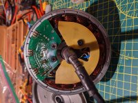
Having opened it up (picture of motor below), I can assert the following:
- The gearing is: Ring gear 78 teeth, Planet gears x 3 @ 30 teeth each on a freewheel clutch plate, Sun gear 18 teeth.
That makes the reduction ratio 4.33(recurring):1
- There are 20 magnets on the outer motor casing.
- There are 18 windings (not sure of terminology here - bits with wire wrapped around them )
)
To set up a Baserunner, I need 1)the motor’s kV in RPM/V, 2)the number of pole pairs in the motor and 3)the maximum phase current
For RPM/V: I've looked at Grin's geared hub motors, and their SX1 is a close-ish match to my motor. The SX1 is 7.4 RPM/V, the documentation says a guess is OK, so I'm assuming that would be as good a guess as any.
For the number of pole pairs, the Grin documentation says " in a geared motor you need to multiply the magnet pairs by the gear ratio". This is where I get unsure. As I said above, there are 20 discrete magnets. So 10 magnet pairs?
And that then makes 40.33... poles? Do I enter the accurate fraction, or just 40? If this is supposed to allow the Baserunner to work out how fast the wheel is turning, rounding this down seems to be introducing an error. So - this is the main thing I am unsure about.
For the maximum phase current, looking at several threads on this forum, for 36V systems like mine, there seems to be a common theme of around 30 amps being a sensible maximum for a hub motor. Is there a safe-ish way to test out a suitable maximum for this motor? Alternatively, if I set the Baserunner maximum high, and then set the Cycle Analyst to limit power at 500 watts, would that be a good approach?
I would be very grateful for any guidance from people who have already travelled this path. Any input appreciated.

https://dillengerelectricbikes.co.uk/collections/street-legal-kits/products/street-legal-electric-bike-kit-samsung-powered-v2
It is now almost four years old, and while it is serving me well, I have decided that I want to start a piecemeal upgrade, starting with a move to a Cycle Analyst V3 and Baserunner_Z9 from Grin. This means that I need to know a few basic parameters for the Baserunner setup, and is the reason for asking the question here. I've done many searches and read many threads, and although some people have posted information close to my needs, I can't find a close enough match to be confident I've got this right. So, thank you in advance for any help.
The motor has one long identifier printed on its case: SY739700CRL0987YS1
That makes it a Shengyi model. I wrote to Dillenger as the OEM, and asked for the model number, or the KV and max phase current - they declined to give me any information about the motor.
Having opened it up (picture of motor below), I can assert the following:
- The gearing is: Ring gear 78 teeth, Planet gears x 3 @ 30 teeth each on a freewheel clutch plate, Sun gear 18 teeth.
That makes the reduction ratio 4.33(recurring):1
- There are 20 magnets on the outer motor casing.
- There are 18 windings (not sure of terminology here - bits with wire wrapped around them
To set up a Baserunner, I need 1)the motor’s kV in RPM/V, 2)the number of pole pairs in the motor and 3)the maximum phase current
For RPM/V: I've looked at Grin's geared hub motors, and their SX1 is a close-ish match to my motor. The SX1 is 7.4 RPM/V, the documentation says a guess is OK, so I'm assuming that would be as good a guess as any.
For the number of pole pairs, the Grin documentation says " in a geared motor you need to multiply the magnet pairs by the gear ratio". This is where I get unsure. As I said above, there are 20 discrete magnets. So 10 magnet pairs?
And that then makes 40.33... poles? Do I enter the accurate fraction, or just 40? If this is supposed to allow the Baserunner to work out how fast the wheel is turning, rounding this down seems to be introducing an error. So - this is the main thing I am unsure about.
For the maximum phase current, looking at several threads on this forum, for 36V systems like mine, there seems to be a common theme of around 30 amps being a sensible maximum for a hub motor. Is there a safe-ish way to test out a suitable maximum for this motor? Alternatively, if I set the Baserunner maximum high, and then set the Cycle Analyst to limit power at 500 watts, would that be a good approach?
I would be very grateful for any guidance from people who have already travelled this path. Any input appreciated.


