Build a mini USV/UPS

izeman said:
These little boards claims 4A output. Sure this is chinese amps, and it will not work converting 5V to 30V@4A, as it's the input current AND the output current that count. But if you say your working battery range is from 9V to 12V and your output is 2A@12V you should be fine.
You can then decide if it's better to down convert 4S to 12V or boost (non fully charged) 3S to 12V.

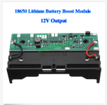
https://www.aliexpress.com/item/DC-DC-Non-Isolated-Step-Up-Module-4-5V-32V-To-5V-42V-Adjustable-4A-Boost/32832844122.html?spm=a2g0s.9042311.0.0.140b4c4dTy5a0W

I have some like that and I think they would be good for this application. Only thing is it will either need to be always on or get switched on when the power fails. I guess it would work to be always on and keep a 4s pack at 4.1v/cell with a power supply that is current limited to a safe charging current.
 
I think something like this should be fine feeding the battery.
Limited to 1A charging they will surely survive :)

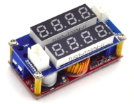
https://www.aliexpress.com/item/5A-Adjustable-Power-CC-CV-2-in-1-XL4015-Step-down-Charge-Module-LED-Driver-Voltmeter/32964535758.html?spm=2114.10010108.1000013.2.381651d2udtbHA&gps-id=pcDetailBottomMoreThisSeller&scm=1007.13339.90158.0&scm_id=1007.13339.90158.0&scm-url=1007.13339.90158.0&pvid=66d3e034-581e-4b82-93dd-45e965e3e01c


Screenshot from 2019-06-15 12-48-50.png
 
So that is feeding the battery for charging purposes.

What circuitry are you thinking to keep the output of the battery normally isolated then bring online to the load when the mains power is cut?
 
A/V?

AC/DC charger / PSU / rectifier I take it?

Set to what voltage?

I think the boost won't be needed unless you prioritize runtime over battery health

If going 3S, that is relatively OK sitting right at or just below 12V, just size the Ah to your desired outage runtime.

Assuming the load devices don't get damaged by LV condition
 
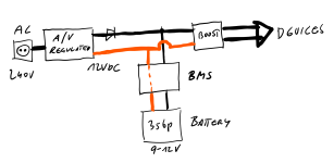
From left to right:

Main's 240VAC goes into a Voltage (V) stabilized and current limited (A) power supply that outputs 12V.
These 12V feed the BMS of the 3s li-ion battery (around 10Ah).
The boost converter comes only into play when there's a power outage - though it's inline all the time (converting 12V input into 12V output ;)). If this happens the battery will feed the boost converter. As time goes by the battery's voltage will drop and the boost converter will raise it to 12V again.
As soon as one cell pack of the battery reaches 3.0V (may take aroubd 3-4h @2.5A) the BMS will cut power.
If in the mean time power comes back the battery will be charged with every current that is left over. Let's say i limit the power supply to 3A then the battery will charge with 0.5A. And even if NO devices are connected the battery can EASILY handle the full 3A charge which is 0.3C.
 
Looks great!

In a situation where loads demand a much higher current than you want to feed the bank, more complexity would be required.
 
Looks like a nice little PCB, but i guess this would not be very energy efficiant? Power input 5V, output 12V. Power output current is quite small as well, so every device would need a seperate one? Any each off them will be powered by a seperate 5V power supply?
But it's for sure a good choice for this one little router/access point that's located away from your main equipment.
 
john61ct said:
PoE gear can be very cheap
What do you mean by that?
I've got some ubiquity wifi stuff here, where APs are PoE powered. So the UPS will include two 24V PoE injectors as well. So basically it will take 12V DC and convert/stabilize it to 12V (ubiquity, cable modem, switch, home security gear), 24V (PoE APs), 5V (Raspberry). This still should be more efficient then 6+ individual AC/DC converters and an AC UPS.
 
Just suggesting a line of enquiry for those not yet aware. Glad to see you are.

Lately I've been sourcing 48V charge sources, and discovered pretty high-amp injectors going for a song.

Great for long distances minimizing power losses.

48V being a standard for telecom racks & data centers, lots of crazy-good quality gear especially powerful rectifier / PSUs at crazy-low pricing.

Picking up constant-current isolated DC-DC converters from 48V input to all the lower-v standard outputs for pennies on the dollar, as in $2 per 20-30A units.

Yes off-topic here, anyone wanting to discuss further, start a new thread.
 
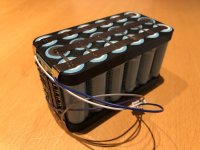
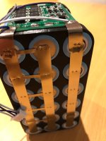
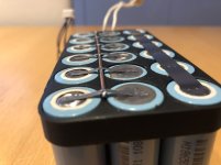
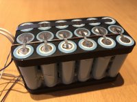
Printed the cell holders yesterday and welded the cells in today. Took 10min. Then the BMS was installed. It's a 40A type. WAY over sized, but I had it at home, and it fits nicely. So i installed it.

Took some pictures of the whole pack. It's completly different than normal ebike packs. Parallel strips are fat, and serial one are small. But this should guarantee a clean melt of the serial connections in case of a damaged cell. The cells have been arranged in a way that all strings are between 12.290 and 12.301mAh.

The balance leads were added to allow a) balancing b) testing of capacity of each string with my UNA6-plus. Testing has just started, but will take a while @1.5A charging and 1A discharging. :lol:

Let the comments fly in 8)


IMG_1708.JPG


IMG_1711.JPG
 
Oh man. I feel REALLY stupid. This will NOT work. :oops:
Just went down to check state of charge and thought ... "HAEHHH?? How is this supposed to work in case of cell failure?!". It CAN'T, as the cell is connected to it's neighbors via a solid nickel strip. DAMN.
I have to do it all again :lol:
 
Even if you did it "right" it may still not work in the event of a cell short. I've seen several Tesla pack fires where the "fuse" wires were apparently not effective. While it doesn't hurt as a safety feature, I'd put more into a fire resistant housing (metal box), especially with a small pack like that.
 
I did a redesign with "fuses" in between. And I agree with you. I'm not sure the fuses will blow in EVERY situation. There may be situation where they should work and others where just all the fuses and the main connection may become hot and nothing else happens. That's why i now made the parallel connection thicker than everything else. This should make sure that enough current can flow from all "good" cells to the one bad cell making the fuse melt.
I will post pictures asap.
 
Back
Top