DIY vivax style.

simon.s

1 mW
Joined
Sep 13, 2017
Messages
17
Location
Frenchy Frenchland
So, been reading here on and off for - well - ages now, and whilst there's a metric shedload of really really good information, there doesn't seem to be much interest in DIYing along the vivax line. I'm guessing that's down to the low power side of things and complexity of the drive system.

Here's my dilemma. My commute to work is 16 kilometers each way, up a class 1 col that the Tour de France hit on a regular basis. As I work at the top of the Col, that means doing a 900m climb in the morning, and a 900m descent in the evening. I'm capable of doing it, but I'm not Lance Armstrong : even on my road bike my average speed is <11km/h going up. That means an hour and a quarter commute, at best, in the morning, so leaving the house at around 5:30 am in order to be there on time, and even that discounts the possibility of a puncture. Given that riding up means reaching work utterly knackered, my job is quite physical and by car it's an easy 20 minutes, it shouldn't be too hard to guess which option gets taken 99% of the time.

Now, we've just bought an "off the shelf" ebike for my wife, a Cube Reaction Hybrid HPA Race 500. Hardtail 29er MTB, 250W Bosch mid-drive. It's a goddamn rocket ship, at least up to 25km/h where the EU regulations kick in and cut off the motor, but too small for me (she needs a small bike, I need a large). Still, last day off, I rode up the col on it, and apart from the uncomfortable aspect of having the saddle too low and my knees scraping the bars as I pedalled, it was kinda fun. Plus, I got to the top without sweating or going above the "eco" assist mode. Actually, that's a bit of a lie, I did briefly try "turbo" mode and it scared the crap out of me. Door to door - 37 minutes.

So, I figure I don't need some 1000W monster, 200W should be more than enough.

So, I'm kinda sold on this. But I'm the kind of guy who likes building stuff, tweaking things, and taking things apart. Plus, I've already got bikes - an early 2000s "Bertin" road bike and a late 90s "Sunn" hardtail MTB. The idea of going totally stealth appeals to me. €2K+ for a vivax install, however, does not appeal to me. Friction drive a la Kepler would be OK, except in winter with studded tyres it might be a bit off.

So, why not do an "in the seat tube" setup myself?

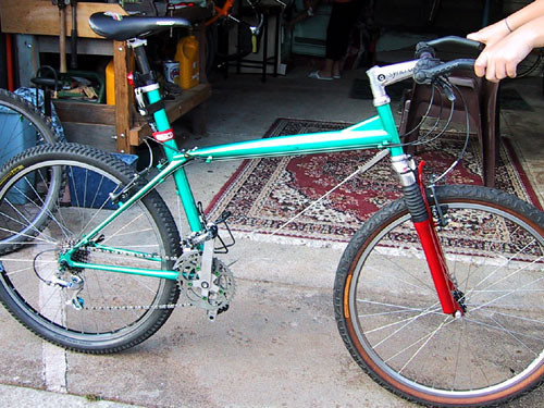
My choice for host bike ideally would be my Sunn - it's already modded for disk brakes, and I can't see myself riding up the col in the snow on 700x23c slick tyres. Otherwise I have a Scott frame lying about, but it doesn't gain me much (more on that later) or I can find a cheap piece of crap to experiment on. I have precision machine tools at home and access to a load of big toys at work (mig, tig, oxy-acetylene, 60 tonne hydraulic press, etc). Tooling and fabricobbling doesn't scare me.

So, what I'm thinking is:

- max ~200W usable power at the crank
- pedal assist, not throttle.
- peak assist power somewhere around the 30-40 rpm mark at the crank (rider struggling), no assist beyond say 90rpm (spinning)
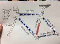
- inrunner motor + planetary gearbox in the seat tube
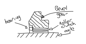
- modified cartridge bottom bracket integrating freewheel and internal drive gear

So, what's the hard bits?

Gearing is pretty easy once I work out the ratios needed. A 3:1 bevel drive on the crank shaft, and a 2 or 3 stage planetary gearbox, job done for a pretty minimal loss of power, a 2 stage planetary and a bevel drive should run somewhere around 90% efficient.
Smaller diameter motors run higher rpms per volt and lower overall power. As an example, for the Turnigy XK series, a 24mm diameter motor gets you 350W at 4700KV, a 28mm diameter motor is 800W at 1980KV, 1400W at 3850KV. But guess whose frames will fit a 24mm motor and not a 28mm motor?
Seat tubes aren't notorious for being well ventilated. Shoving a motor down there and running it full chat is liable to result in an expensive meltdown. It seems to me that running, for example, a 1400W motor a quarter of it's rated peak amperage should be a win, over running a 350W motor at 100%, no?
Smaller motors want less volts. Less volts = less weighty (and less expensive) battery packs. Using the turnigy motors again, 24mm motor = 3S pack, 28mm motor = 4S pack. 10AH of 3S pack should be able to be hidden under the seat, or in a bottle cage tool pack type thing.
I don't want a throttle, just pedal assist and a subtle on/off switch. Butchering the bottom bracket probably precludes using a BB with inbuilt torque sensor, though. Not sure about where to go with that, or what solutions exist.
Hell if I know what to use controller-wise. I'm guessing a straight RC ESC ain't gonna cut it.

There's probably a bunch of stuff I'm missing here, or just plain wrong about. Please feel free to enlighten me, tell me I'm an idiot, etc.
 
simon.s said:
So, been reading here on and off for - well - ages now, and whilst there's a metric shedload of really really good information, there doesn't seem to be much interest in DIYing along the vivax line

Ha, i had and still have interest.

trough my interest i even destroid an existing Gruber (former vivax) kit.
First the Controller by a stupid mistake, later i burnt the Motor with a 10s VESC and FOC at 350 Watts with hand-throttle.
(But the VESC-Throttle Vivax was amazing. the Motor and Gears could stand teh 350 Watts for several Rides in BLDC but when i made a try in FOC the Motor fried at the first run)

But i still do not want to give up.
But what i can tell you is thats it actually will just be enthusiasm, caus buying just the Motor-gears unit from vivax is around 1300€, that will also be the maoney youll spend into material and time making it by yourself, but sure thats why we have this forum here.

So i'll be away for one week but after that i can send you some photos from my fried setup and teh takedown of avivax and its gears.

in the German Pedelforum there were thought about doing it in DIY but i think all of them gave up cause of to high costs on the single parts.
https://www.pedelecforum.de/forum/i...tive-zu-gruber-assist.9678/page-7#post-484500

i can tell you that the Motor and Gears used in VIVAX are MAXXON parts (made in swiss so guess what)
https://www.maxonmotor.com/maxon/view/content/products

The Motor could also be slim RC-Motor if you accept enormous sound coming from it.
So my first Gruber-Vivax Motor was really enoiing loud compared to the new one nowadays.
So i guess it well be hard to catch up with all the developement Vivax did over the Years in DIY.

whenever i would have money left id buy a motor-Gear unit with the Bevel for the Hollowtech-Crank and connect it to a VESC and throttle (like i had it for maybe 5 Runs).
 
simon.s said:
Please feel free to enlighten me, tell me I'm an idiot, etc.

Ok if its you wish -> you are an idiot ;)

VESC (X,6), or FOCbox is the ESC to go, do not try an RC ESC you need to be able to tweak around.

and i'm not sure about your less-cells-in-series-lower-weight-theorie it always about th Wh of a pack and they do not change id 3s4p or 12s1p but efficiency of motors depend on specific Volts so youd have to go from there and not planning on low Voltage Packs.

cause low Voltage Means higher Amps -> 200Watt can be 2Volts 100Amps or 100Volts 2 Amps ->Amps are producing motor heat
 
Ah, yeah, hadn't thought about noise.

There's 3 components to the noise produced :

1 - motor noise. I suspect this is the most important. This can be attenuated by using quieter motors (duh), slower running motors (by undervolting a larger motor, for example) and by using an FOC driver. For an example, of the effect of the latter, see Kepler's videos posted in his "comes of age" thread, the difference between the vesc in FOC mode and the other controllers is astounding.

2 - gearbox noise. This will be affected by noise in the motor drive, FOC mode will also help here. Otherwise, it's gear meshing noise, more from the faster end of the gearbox. Again, a slower running motor will reduce noise, by both reducing the speed of the input end, but also potentially by reducing the number of stages in the gearbox. Most planetary gearboxes are run "dry" with some grease; running "wet", filled with transmission oil, will also reduce noise (although it may also reduce efficiency)

3 - Final drive noise, output of gearbox to bottom bracket shaft. Bevel gears, there will be some noise, not much you can do about it unless it's possible produce an oil-filled cartridge bottom bracket with integrated drive gearing and freewheel system. This might be possible, but it's gonna be super hard to do DIY.

I think tolerable noise should be do-able DIY, but my gut feel is that the smaller the seat tube Ø, the louder it's gonna be.

In terms of cost, I can't see it being anywhere near the cost of the vivax / gruber's setup.

Let's take the example of a 30.9mm seat tube. We need a motor and gearbox that will fit in there, and a drive that will fit in the bottom bracket.

For the motor, let's take an XK2845-1980. It'll go in, it's relatively slow, it'll run FOC, ~800W run full chat. Price - $20

The bottom bracket is going to require some machining, but max Ø for the driven shaft bevel gear is 34mm. Ebay, aliexpress, etc, if you're spending more than 15 bucks you're being ripped off. Sadly, most angle grinder drives (which have spiral bevel gears) are too big. A bigger reduction here potentially means less gears in the gearbox. The bevel gear needs to fix to the shaft via a freewheel mechanism. Forget gutting a clackity bicycle freewheel with pawls, a roller clutch / one way bearing is the tool for the job. Again, cheap, 15 - 20 bucks max.

The spendy bit is the gearbox. It needs to be pretty much industrial, but we can probably live with plastic gears at the high speed end (less noise). Still, by "spendy", it's not that bad. Let's assume we are using the motor above, undervolting to a 3s pack, 11.1V, that's 22,000 rpm unloaded (that's still close to 300W motor output at full amperage). Assume ~75% of speed under load, 16,000 rpm. We want to get that down to, say, 90rpm max, if we have a 3:1 reduce on the shaft, we need 270rpm out, about a 60:1 reduction. 28mm seems to be a standard size for electric scooter drives, as it happens; planetary drives for that purpose go around a hundred bucks on aliexpress, even a Maxon drive is "only" around 250 CHF.

A couple of hundred bucks and some machining time, it's not too expensive.

I think I'm gonna have to try and find a junker with a 30.9 seat post
 
I'm subscribing to see how you will build this into the seat tube and driving the bottom bracket. Good luck and keep us posted.
 
SlowCo said:
I'm subscribing to see how you will build this into the seat tube and driving the bottom bracket. Good luck and keep us posted.
You might have to wait a while, this is liable to be a "slow burn".

For mounting, I'm thinking a steel or aluminium (probably alu for heat dissipation) sleeve for the motor and gearbox, machined to an OD a couple of 100ths of a mm or so less than the seat tube ID, drill out the water bottle rivnuts on the frame seat tube and use the holes to fix the sleeve. I'd worry about the torque of the motor ovalising the frame holes, though.

Potentially, I could run a rectangular section rod down the front of the seat tube, married to a milled slot in the sleeve. That rod can be plug welded in place along its length, and one or two through bolts to hold the motor / gearbox assembly at height.

Mustn't forget a hook on the top to be able to pull the whole shebang out without pulling on the (potentially burnt out) wires :)
 
Aren't you just trying to reinvent the wheel, why not buy a TDSZ2 250W and you have all you want + a gear system to keep the cadence nice without all the pitfalls of the bevel gear set up which creates drag when the battery is flat.

Unless of course you fancy the machine work and design experience ?
 
Of course I'm reinventing the wheel. In this case, an enormously expensive wheel.

Sure, I could buy a bottom bracket kit, hang a load of batteries off the frame and end up with something ugly and heavy that rides right now (well, as soon as the post gets it to me, but hey).

What I'm aiming for is something that is light (I'm aiming for 2 kilos max, including batteries), invisible (or as near to it as possible), ridable off road / in rain, mud and snow, and possible to pull off the bike in under 2 minutes. If it wasn't for the last 2 targets, I'd have a kepler drive on there right now.

As for drag with flat batteries, it shouldn't be appreciable. After all, you don't notice the extra drag of your freewheel when coasting, do you? Once the batteries are flat, I'd rather work against a needle bearing's intrinsic drag than haul around getting on for an extra 10 kilos of motor and batteries. If I can get this right, the only sign that this is an ebike apart from a couple of wires coming out under the saddle should be that you can't backpedal it.
 
Waynemarlow said:
You may want to look up just how much friction there's on a bevel drive especially once you get over 40:1, just saying
Firstly, you're mixing efficiency and friction. Yes, high-ratio bevel drives, especially if they aren't hypoid, are low efficiency. But I'm not talking high ratio for the bevel drive, 3:1, maybe 4:1 max - at that point they are 90-95% efficient, friction shouldn't be an issue - we're turning at a low speed - if we max out at 120rpm crank, that makes the input maybe 500rpm.

If friction were an issue with bevel drives, a major failure mode for angle grinders would be melted gear housings - they run about 10.5:1 through a hypoid bevel gear, and driven speed is around 12,000 rpm on a 115mm version - I'll let you work out the input speed. How does it go? Ah, yes. "Just saying".

The higher we push the ratio of the bevel drive (within the bounds of a max ~34mmØ for the driven gear), the less we need to reduce with the planetary drive, the sweet spot is where the bevel knocks out a stage on the planetary.

All of which is academic, because with the motor off or running the driven bevel slower than the axle, it simply won't be connected. Here's a crappy mousecad drawing. We could replace the bearing with a one way bearing and the roller clutch with a roller bearing to the same effect. Effectively we mount the bevel drive in the same way your cassette is mounted to the rear axle - transfers torque in one direction, freewheels in the other.

file.php


Yeh, the roller clutch / one way bearing is a weak point in the chain. Still, they're pretty tough, the ones we use at work are rated for the job of stopping 180 kilos at 10m/s driven through a 160mm radius in under a second, something like 1800N * 0.16 = 288NM. Given that 180kilos includes potentially two adult humans, I suspect they are seriously overspecced.
 

Attachments

  • Drawing.png
    Drawing.png
    7.3 KB · Views: 3,373
Yes the gears are reasonably efficient under normal situations with an engine driving the output. When "you" are turning the output, turning the input of the system then they are pretty inefficient particularly if they are hypoid. Yes I know you have a one way clutch bearing in there but you also have very little room as in diameter to play with and thus you will need quite a big bearing to handle the load, we looked for some time and couldn't find a suitable small diameter bearing that would go into a housing and into the downtube, things may have changed as that was a couple of years ago.

The other thing we found was that although the Vivax was rating themselves as 200W, all the reports came back that they were actually under 100W's of energy at the crank, we stopped at that point as we felt for what we needed the power for, it was probably in excess of 200W (mtb ing ). Good for lightweight hill assist on fast road bikes, but pants for anything meaningful.

Good luck though as things change and new motors and materials arrive on the scene and a fresh eye often brings up new ways of doing things.
 
Waynemarlow said:
Yes I know you have a one way clutch bearing in there but you also have very little room as in diameter to play with and thus you will need quite a big bearing to handle the load, we looked for some time and couldn't find a suitable small diameter bearing that would go into a housing and into the downtube, things may have changed as that was a couple of years ago.
I think if you're looking to put 200W or more into the crank through a or several bearings, things might get sticky. Torque = 9.5488 * kW * rpm, so if we assume 100W and peak power at 30-60rpm, we need to handle about 60N.m, that's in spec (although towards the upper end) for (for example) an HFL2520 from NTN (25mm ID, 32mm OD, 30mm long). Bung an HF2520 in there as well (20mm wide, but with no axial load bearing) and you can handle 130N.m, that's enough for about 230W at the crank (so assuming 50% losses in the geartrain, not unreasonable given what vivax does, that's 500W "for marketing purposes", i.e. motor, and more than I can cram into a 27mm seat tube). From memory the sprag clutch stuff can take more "welly", but it's a much harder fit, they're standard bearing sized and stuff that you can cram into a BB is low rated. Then there's the option of gutting a freehub - they can *definitely* take the hit.

Waynemarlow said:
we stopped at that point as we felt for what we needed the power for, it was probably in excess of 200W (mtb
I thing it largely depends what you want. I'm after assist, not a motorcycle - I've already got a couple of those, powered by petrol, with a much more acceptable range than anything the electrics can deliver at the moment - and although mountain biking is more "peaky" in terms of power output, if it means a given ride goes from an average of 200W rider input with peaks of 3-400W to an average of 100W rider input with peaks of 2-300W, hey, it's still a win. You're still gonna sweat, but not nearly as much.

I still think the main problem is "how much power you can cram into the seat tube". It needs to be slim, slim motors have less power and run faster, so more noise, more gearing and thus more loss, and so on. If I could figure out a way of opening up the downtube without buggering structural integrity, I could get a 42mm motor in the Scott frame I have to hand. It would make *everything* easier.

It's a juggling act.
 
On FB, in the Fast Electric Bike group, I posted a very similar question about a month ago, and put a pic showing what I was hoping for. I'm not nearly as knowledgeable about the technical or engineering aspects as you guys judging by the information posted so far.

With that said, I went to a bike shop that sells various frames, and looking at some of them, I noticed that some of the down tubes are significantly larger than the seat tubes. Additionally, many of the down tubes in those frames have a hole in the BB just as the seat tube does, which makes me believe that it should be possible to use the same gear on the BB Vivax style, but use a larger motor in the down tube instead of the seat tube.

I do realize that getting the motor into the down tube is going to require the frame to be cut, but if you are using a steel frame, it shouldn't be too difficult with a decent welder.

Am I an idiot and out of my mind by missing something? :lol:

Edit: Just saw your post about the down tube Simon :)
 
Cutting into the downtube and then welding it back up would be doable, but leaves you with a totally inaccessible / unserviceable motor. Leaving it open is going to result in a bent bike (not to mention obviating one of the advantages of shoving it all in the frame in the first place, weatherproofing). That said, there was / is the Slingshot.

337329_23d2d32104.jpg


Yea, that's a wire downtube, and a hinged top tube. Cray-zee, man. I rode one, once - it's kinda like a URT suspension bike with a really high pivot. And floptacular, a noodle.

Most of the stresses in a normal downtube in normal use are tension, but there's a big bending moment at the head tube junction (a major failure point for aluminium frames) every time you hit a bump, and a fair amount of torsion at the lower end if you get up and really crank that mother. I'd be really, really, worried about opening up the downtube. The head tube, on the other hand, might be possible. It's short, massively supported by the top tube and down tube, and it's in compression via the head bearings - one might potentially "holesaw" through the front and into the downtube, then use a removable sleeve over it to deal with the compression forces. It might just work. Plenty of room for stowing batteries without interfering with stuff like dropper posts, too. And if you want moar powarr, you're already cutting into the downtube, why not go the whole hog and cut into the top tube as well :)

Hrrrrrrrrrm...
 
Wow, that bike looks like the way I felt when I shaved off my beard and looked in the mirror (mole rat). I instantly lost half my testosterone. Thanks a lot Gillette.

The hole in the head tube sounds like a good idea though. the motor could just slide through it as it would through the seat post.
 

Attachments

  • S__6922387.jpg
    S__6922387.jpg
    119.9 KB · Views: 2,399
Back
Top