Switching a ebike controller to a e scooter controller

soprano_415

10 µW
Joined
Feb 11, 2024
Messages
6
Location
San Francisco, CA
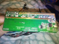
My main objective here is to connect my leads. I saw a previous post similar to mine and a response was to write down the numbers/letters on the controller so I've gone ahead and done that and I've attached it to the post. (i attached a picture of the side I wrote down)

Controller A
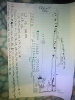
1000000074.jpgIMG_20240211_023252_312.jpgIMG_20240211_023326_473.jpg


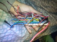
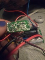
Okay so below is a picture of the the leads I'm trying to connect to thru the controller In the first half of my post. The controllers have different colors wires so I need to know where the wires from controller "B" connect to on controller "A"

Controller B
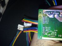
IMG_20240211_035351_400.jpg

I want to say in advance that I appreciate any help that any of you could provide to me so thank you!
 
Your Controller A seems to be a sensorless square wave controller from Lishui. The motor halls are connected to pads SA, SB, SC normally. These pads are missing on the PCB

Your controller B has connectors for the motor halls. So perhaps it can't work sensorless. If your motor has no hall sensors, controller B may not be compatible with you motor.

Scooters are normally driven by UART commands coming from the dashboard. E-Bike controllers are driven by throttle or PAS/torquesensor, that are attached to the controller directly....

regards
stancecoke
So is it not possible to connect the leads from con. B to con. A then?

Thank you for your response, your help is very much appreciated!
 
So is it not possible to connect the leads from con. B to con. A then?

Thank you for your response, your help is very much appreciated!
Also I forgot to mention this before the reason I want to connect them is because con. B has a blown fuse somewhere i believe, and con. A is my only other controller i have available to use. And I need con. A to be able to connect to con. Bs battery
 
Of course it is possible.
You need at least the battery, the three phase wires and the throttle connected.
The throttle signal has to be connected to pin "SP". +5V and Gnd to the red and the black wire of the throttle connector.
To switch on the controller, "SW" (blue wire normally) has to be connected to VB+
With this minimum wiring, the motor should start by operating the throttle.
Perhaps the hallsensor signals from the motor have to be connected to HA, HB, HC. With +5V and GND on the red and the black wire of the hallsensor connector.
But if they are needed, it might be a little tricky to find the right hallsensor/phase combination.

regards
stancecoke
Thank you very much for that it's really what I needed to get it going
 
Of course it is possible.
You need at least the battery, the three phase wires and the throttle connected.
The throttle signal has to be connected to pin "SP". +5V and Gnd to the red and the black wire of the throttle connector.
To switch on the controller, "SW" (blue wire normally) has to be connected to VB+
With this minimum wiring, the motor should start by operating the throttle.
Perhaps the hallsensor signals from the motor have to be connected to HA, HB, HC. With +5V and GND on the red and the black wire of the hallsensor connector.
But if they are needed, it might be a little tricky to find the right hallsensor/phase combination.

regards
stancecoke
Thank you so much you've been super helpful I appreciate it!

One last thing do you know what this is for and if so will I need to use it to do what I'm tryna do and if yes how do I use it ? Thank you again IMG_20240212_061033_198.jpg
 
Back
Top