2007blueprius
100 W
- Joined
- Jun 17, 2013
- Messages
- 258
or at least this is what this thing is supposed to be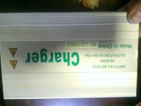
it was intended to charge a 48v 80 ah pack Lifepo4 pack, long storry but common concept within the users forum it is adequate ( I am not sure about that so I took it apart and brought it here ), I am not even sure what category this charger falls into, but for the most part it is advertised as a dumb charger 55.5 v at 15 amp non adjustable.
now I do not know much but I have tinkered with PC power supplyes and this looks to me very simmilar, I want to say it is a plain SMPS much simpler than a computer one since it only has one output, that beeing said voltages and amperages should be adjustable to a degree. and heres some pics :
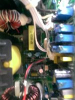
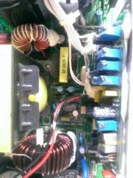
this looks like a control daughter board and I don't know but there are a lot of turn pots there, also couple of these chips are labeled lm 324n, I came across that label before, I think they are used for voltage regulation
otherwise here are some more pics as to the rest of the components:
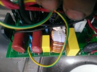
This section looks very simmilar to any PC power supply, I don't remember what to call all these components ( can you tell I am a bit green at all this? ) but from what I read about SMPS this section has some smoothing components, capacitors, I think there is 2 bridge rectifiers, at least one I could recognise, so in theory this section converts 110v AC to 220V DC ( feel free to corect me at any time)
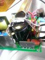
there's the 2 large caps and what I think to be the bridge rectifier
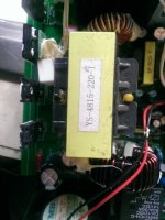
the large transformer and a bunch a switching FET's ( or so I believe they are called )
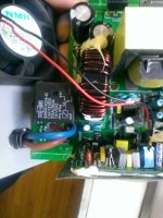
this is the output section, another one of those smoothing coils ( I realy don't know the proper term ), what looks to be like a relay, probl to finish charge I guess
The backside :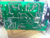
ok so why tinker with it? It does work, but is is really suited for charging lithium chemistry in the first place?
the kit it came out of is a cheap knockoff, nothing about it seems right, I have been lurking on this forum for years reading about everything I could understand and as soon as I got this kit it dawned on me right away that this is nothing like I have been reading it should be.
It is from a plugin kit for a toyota prius, the pack is made out of 16 blocks in series, each block made out of 4 rfe 20 ah pouches,
The system is functional and I bought it used, it has allready destroyed a pack at that time, and it is not a fluke these were never reliable, there is no charge control just first cell to hit HVC ends the charge,
now that I got a replacement pack I would like to set it up properly and get long term use out of it.
I have read that a proper lithium charger is CC/CV there are stages, and I do not think this one does not do any of that.
my understanding is initially they cet charged in CC stage as the charge gets toward the end it is swithced ti CV mode than the amps turned down, so a charge balancer can even the cells, zenid I think is a brand of charger that works in such manner.
It has been suggested to me that lowering the charge current towards the end of charge ( even manually )will help in the top off process, so that is why I opened it to see if I can do that, but I do not know enough to acomplish such a task
also in a perfect world 55.5v/16 = 3.46875v per block, bit low for lithium, I believe the norm is 3.9, the bms ( if you can call it that) that came with it had a HVC set for 3.8v, even that proved to be too high for these cells, considering charging 80 ah blocks at 15 amps that is 0.1875c, among users 3.65v should be max, most ate confortable with even less for longevity purposses, also the rest of the system seems to be a joke there is no balancing at all, common practice is to manualy perform a bottom ballance every 6 months, and rely on HVC in the mean time.
I have not been able to find any diagram or model number, http://www.enginer.us is the manufacturers website and while it is still active they are out of bussiness.
Anywho I could use some help with this, I can take some better pictures but wont be able to post them here, I have a photobucket account for this project http://s1365.photobucket.com/user/2007blueprius/library/?sort=3&page=1#/user/2007blueprius/library/?sort=3&page=1&_suid=138519090894007512453209954883
let me know what you all think and wether you have a clue how to porced or if I need to zoom in on any components, here's an overview:

it was intended to charge a 48v 80 ah pack Lifepo4 pack, long storry but common concept within the users forum it is adequate ( I am not sure about that so I took it apart and brought it here ), I am not even sure what category this charger falls into, but for the most part it is advertised as a dumb charger 55.5 v at 15 amp non adjustable.
now I do not know much but I have tinkered with PC power supplyes and this looks to me very simmilar, I want to say it is a plain SMPS much simpler than a computer one since it only has one output, that beeing said voltages and amperages should be adjustable to a degree. and heres some pics :


this looks like a control daughter board and I don't know but there are a lot of turn pots there, also couple of these chips are labeled lm 324n, I came across that label before, I think they are used for voltage regulation
otherwise here are some more pics as to the rest of the components:

This section looks very simmilar to any PC power supply, I don't remember what to call all these components ( can you tell I am a bit green at all this? ) but from what I read about SMPS this section has some smoothing components, capacitors, I think there is 2 bridge rectifiers, at least one I could recognise, so in theory this section converts 110v AC to 220V DC ( feel free to corect me at any time)

there's the 2 large caps and what I think to be the bridge rectifier

the large transformer and a bunch a switching FET's ( or so I believe they are called )

this is the output section, another one of those smoothing coils ( I realy don't know the proper term ), what looks to be like a relay, probl to finish charge I guess
The backside :

ok so why tinker with it? It does work, but is is really suited for charging lithium chemistry in the first place?
the kit it came out of is a cheap knockoff, nothing about it seems right, I have been lurking on this forum for years reading about everything I could understand and as soon as I got this kit it dawned on me right away that this is nothing like I have been reading it should be.
It is from a plugin kit for a toyota prius, the pack is made out of 16 blocks in series, each block made out of 4 rfe 20 ah pouches,
The system is functional and I bought it used, it has allready destroyed a pack at that time, and it is not a fluke these were never reliable, there is no charge control just first cell to hit HVC ends the charge,
now that I got a replacement pack I would like to set it up properly and get long term use out of it.
I have read that a proper lithium charger is CC/CV there are stages, and I do not think this one does not do any of that.
my understanding is initially they cet charged in CC stage as the charge gets toward the end it is swithced ti CV mode than the amps turned down, so a charge balancer can even the cells, zenid I think is a brand of charger that works in such manner.
It has been suggested to me that lowering the charge current towards the end of charge ( even manually )will help in the top off process, so that is why I opened it to see if I can do that, but I do not know enough to acomplish such a task
also in a perfect world 55.5v/16 = 3.46875v per block, bit low for lithium, I believe the norm is 3.9, the bms ( if you can call it that) that came with it had a HVC set for 3.8v, even that proved to be too high for these cells, considering charging 80 ah blocks at 15 amps that is 0.1875c, among users 3.65v should be max, most ate confortable with even less for longevity purposses, also the rest of the system seems to be a joke there is no balancing at all, common practice is to manualy perform a bottom ballance every 6 months, and rely on HVC in the mean time.
I have not been able to find any diagram or model number, http://www.enginer.us is the manufacturers website and while it is still active they are out of bussiness.
Anywho I could use some help with this, I can take some better pictures but wont be able to post them here, I have a photobucket account for this project http://s1365.photobucket.com/user/2007blueprius/library/?sort=3&page=1#/user/2007blueprius/library/?sort=3&page=1&_suid=138519090894007512453209954883
let me know what you all think and wether you have a clue how to porced or if I need to zoom in on any components, here's an overview:


![WP_20131124_005[1].jpg](/sphere/data/attachments/68/68290-d5f4e765aab299f9ab6c5d4874247500.jpg)
![WP_20131124_004[1].jpg](/sphere/data/attachments/68/68291-d3e55c0d99a1caffeca8ff14bfd1560d.jpg)