agniusm
1 MW
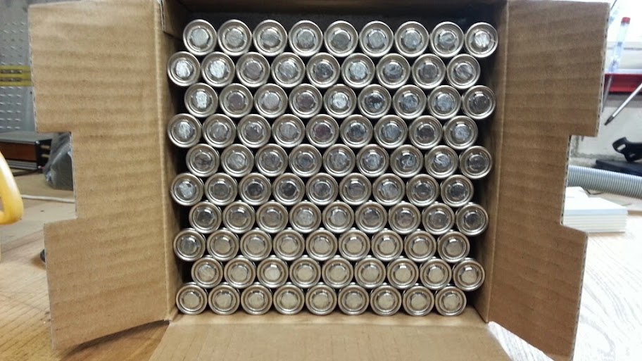
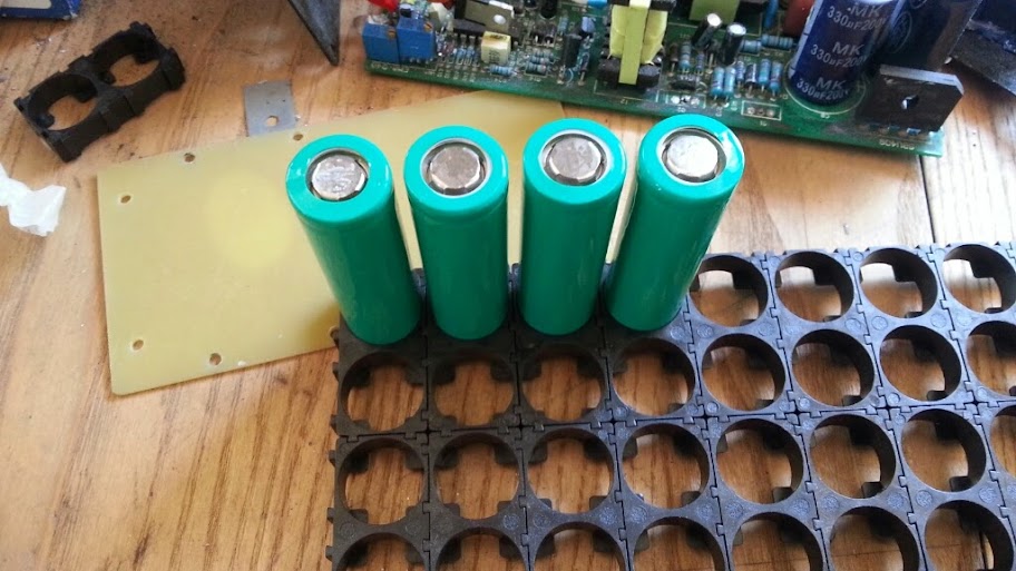
Cells ripped out of the damaged pack:
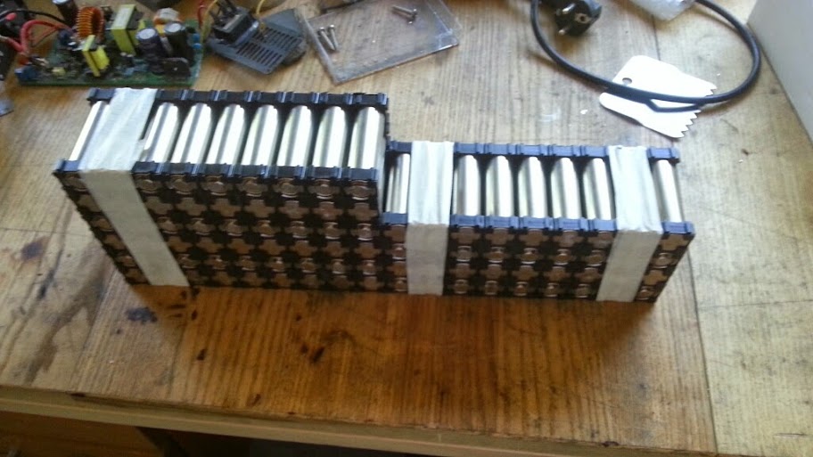
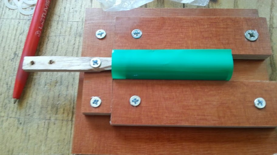
Making the shape:

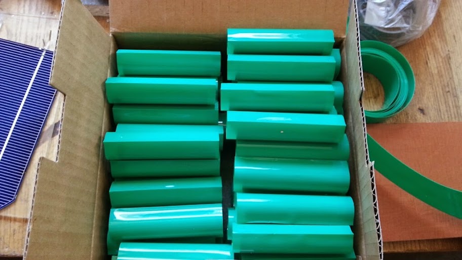
Re-wrap:
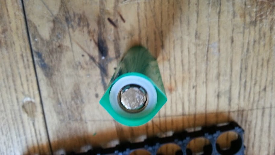
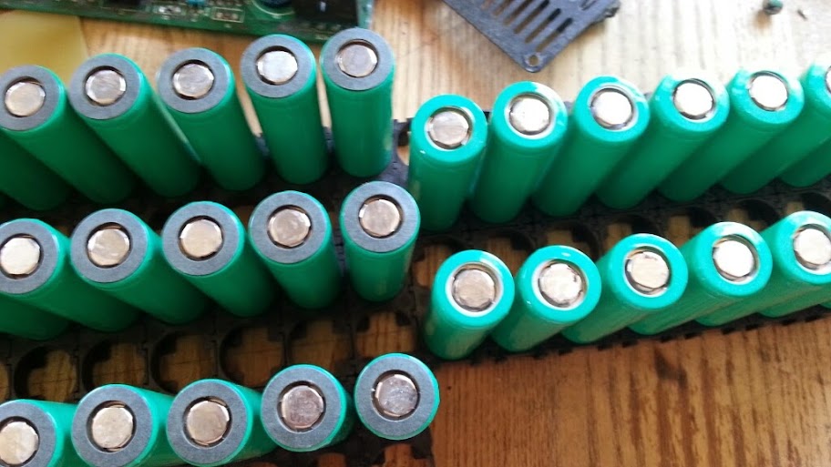
Internal insulator replaced:
For consistency:
Beginning:
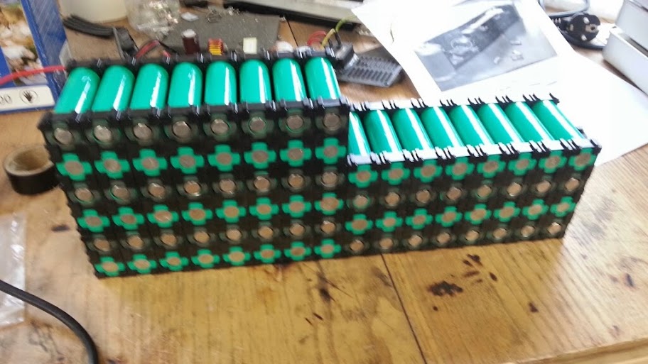
Placing additional insulator:
Done:
Specs:
Cell: Valence IFR-18650EC 1350mAh (i am a bit confuse as whether this cell is 3.2V or 3.7V nominal or both)
After 2 year use (summer season) gives full rated capacity at 1.5C
(according to unofficial talks, cells are capable up to 8C but i dont know if this is reliable info. If any one knows more please do share, cause i need to pick a BMS, the right power)
Cell holders, tab material and insulation gaskets from supower.
Internal insulation gasket reused
Shrink tube from ebay, PVC, size D20mm, best cut to 72mm. Replaced shrink tube is twice the thickness, feels better.
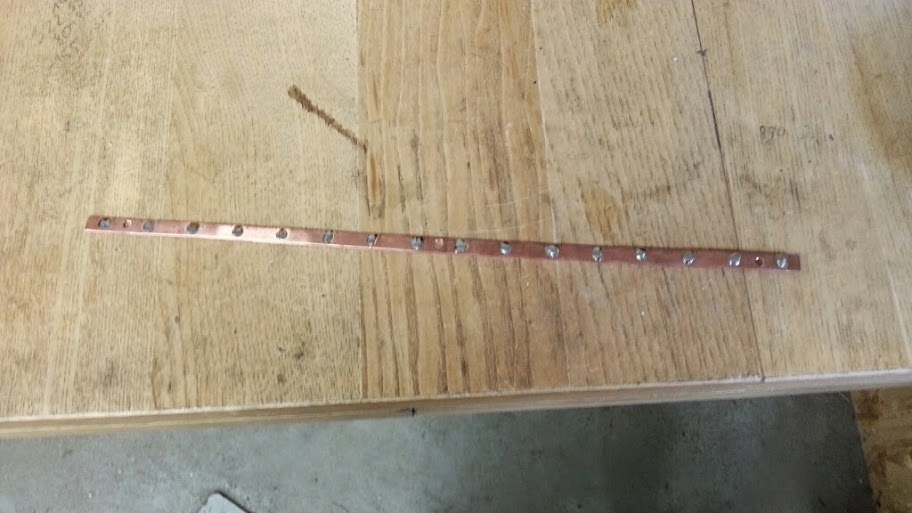
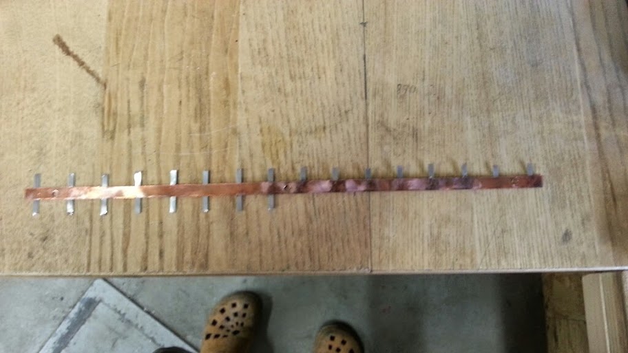
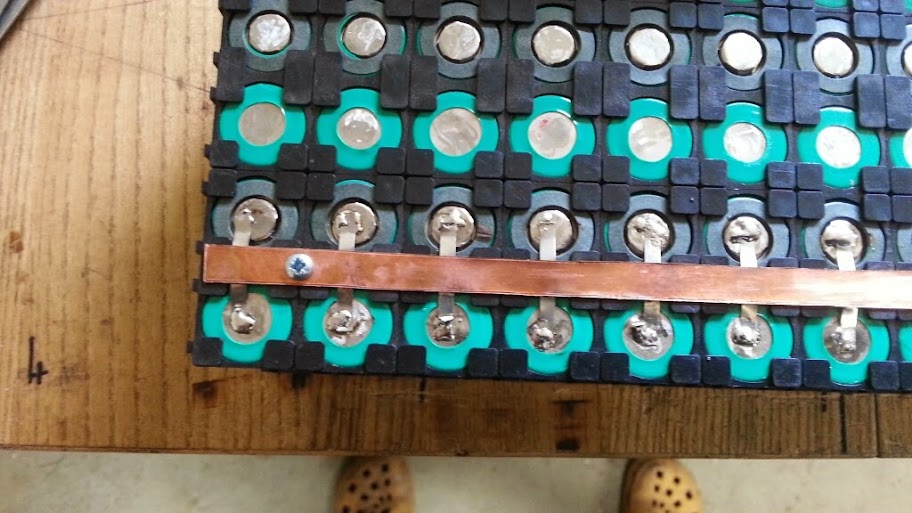
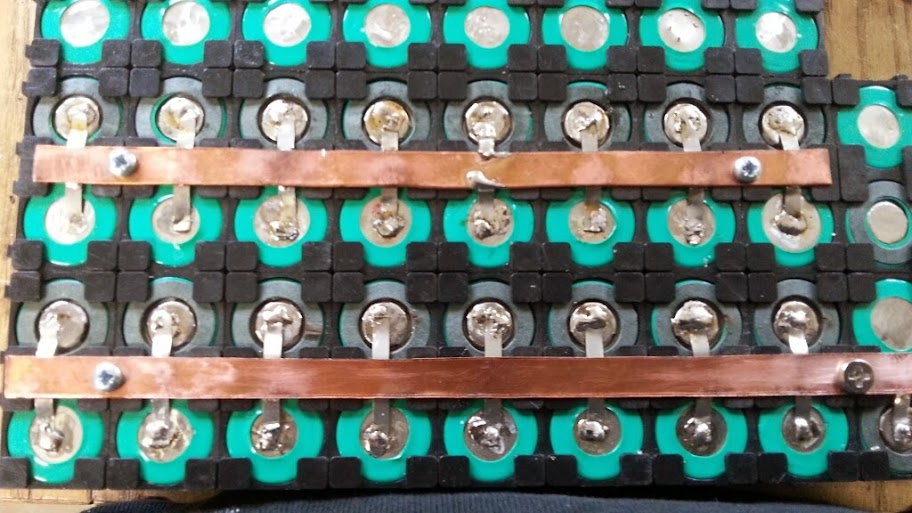
Thinking of ways to terminate the pack. It will be soldering, but i will use 4mm nicket tab material soldered to main copper bus and cell so minimal heat builds up. I have tested and as soon as you remove soldering iron you can touch soldered surface and it is barely warm, so i assume that cell outer case absorbs heat without doing damage to cell internals.
I will update as soon as i will finalize interconnect method. Good stuff.
P.S. Attached cell spec. Looks like it is 3.2V nominal but can be charged to 4.2V, confusing")
Looks like pulse discharge is 7A so 5C for 30 seconds, and 2C continuous max.
View attachment 18650ec_li_ion_cell_3_2v_1_5ah_lifepo4_cells-92334648.pdf
...so i am guesstimating that 30-35A should be the limit on the controller and BMS
Making the shape:
Re-wrap:
Internal insulator replaced:
For consistency:
Beginning:
Placing additional insulator:
Done:
Specs:
Cell: Valence IFR-18650EC 1350mAh (i am a bit confuse as whether this cell is 3.2V or 3.7V nominal or both)
After 2 year use (summer season) gives full rated capacity at 1.5C
(according to unofficial talks, cells are capable up to 8C but i dont know if this is reliable info. If any one knows more please do share, cause i need to pick a BMS, the right power)
Cell holders, tab material and insulation gaskets from supower.
Internal insulation gasket reused
Shrink tube from ebay, PVC, size D20mm, best cut to 72mm. Replaced shrink tube is twice the thickness, feels better.
Thinking of ways to terminate the pack. It will be soldering, but i will use 4mm nicket tab material soldered to main copper bus and cell so minimal heat builds up. I have tested and as soon as you remove soldering iron you can touch soldered surface and it is barely warm, so i assume that cell outer case absorbs heat without doing damage to cell internals.
I will update as soon as i will finalize interconnect method. Good stuff.
P.S. Attached cell spec. Looks like it is 3.2V nominal but can be charged to 4.2V, confusing
Looks like pulse discharge is 7A so 5C for 30 seconds, and 2C continuous max.
View attachment 18650ec_li_ion_cell_3_2v_1_5ah_lifepo4_cells-92334648.pdf
...so i am guesstimating that 30-35A should be the limit on the controller and BMS