EasyDIY OpenSource display for EVs: TSDZ2 and Bafang M500/M600 EBike motors

General Discussion about electric vehicles.
casainho   100 GW

100 GW
Posts: 5977
Joined: Feb 14 2011 2:43pm

Re: EasyDIY OpenSource display for EVs: TSDZ2 and Bafang M500/M600 EBike motors

Post by casainho » Jan 17 2023 4:03am

martinn27 wrote:
Jan 17 2023 2:34am
Hello everyone, I need your help. I studied in detail the instructions on how to build this display, but I can't flash the bootloader with stlink v2 (V2.J40.S7)
I suspect that I can't get in because "Warn : target nrf52.cpu examination failed"
nrf52840 (PCA10059 , 2.1.0 , 2022.9)
I also don't know how to proceed with telnet communication and whether stlink v2 needs to be modified or is it enough if I have stock firmware
Hi Martin.

The good news is that OpenOCD seems is working well, connecting as expected to NRF52.

On Linux, I do on a terminal:

telnet localhost 4444

Then I get inside telnet and I can run OpenOCD commands. You can do "help" to get help from OpenOCD commands. Then you will see the commands for flash, erase, etc. You can also search on google but you will figure out what are the commands and parameters.

Are you building the display for TSDZ2 or Bafang?

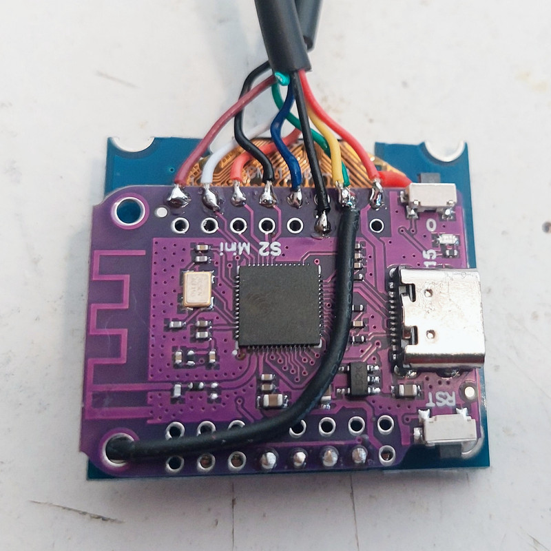
I am developing a new version of the display, but I will only test / develop for my Bafang M500. The most important change is that it runs Pyhton firmware and uses the ESP32-S2 (first programming is done with a USBC cable, then it is wireless). It is also programmed by wireless, I can edit the Pyhton firmware file directly with my phone!! More details:

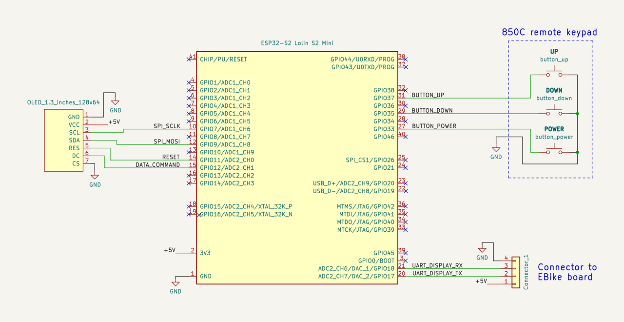
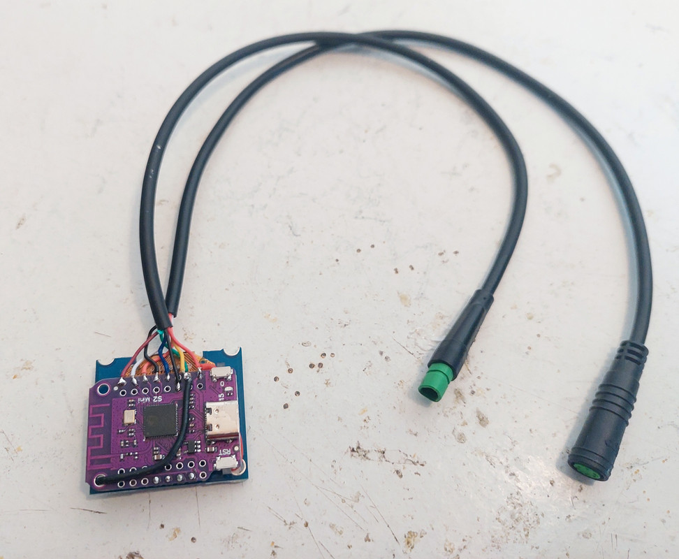
The schematic is so simple!! Only 11 wires to solder:

Image

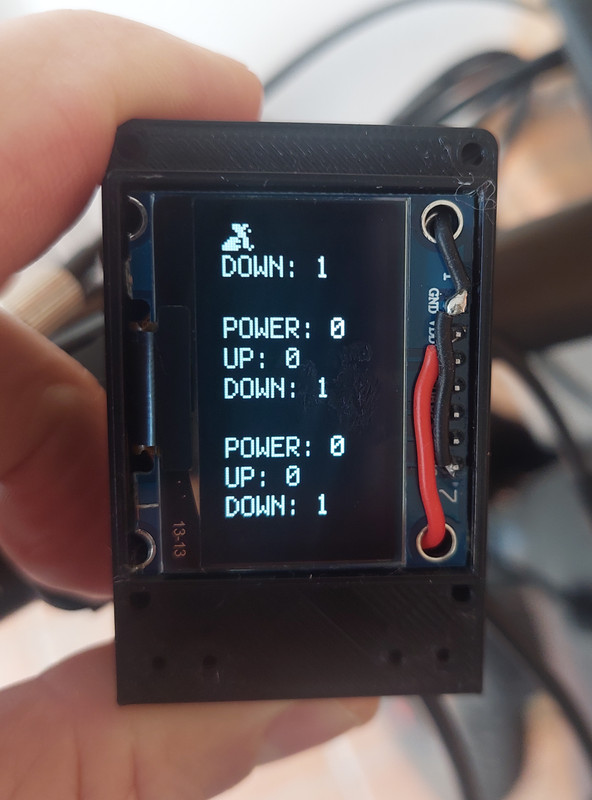
I already tested and it works. Early tests showing the state of POWER, UP and DOWN buttons:

Image

Details of the build.
One connector is the display connector to the original Bafang M500 harness cable. The other round connector is to connect to the 860C display remote keypad I bought on Aliexpress:
Image

Image

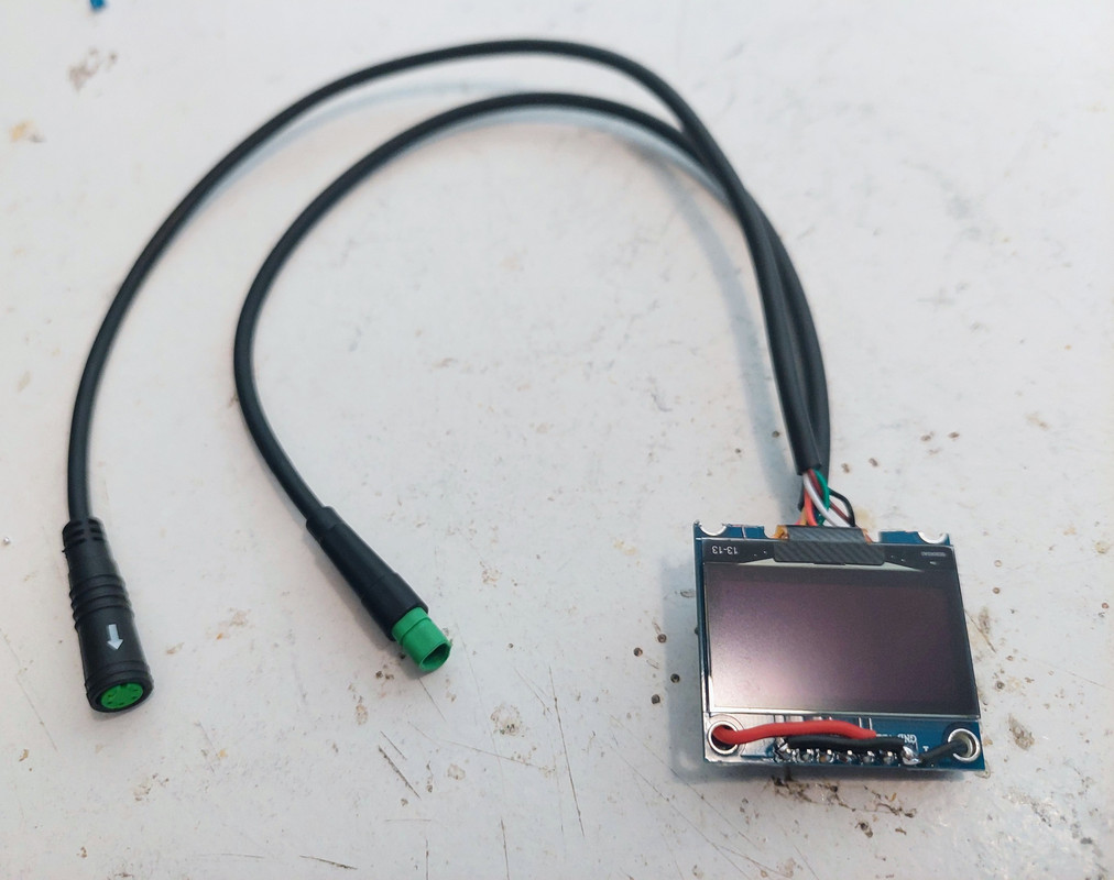
Very clean and simple:
Image

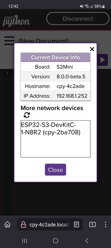
And now there are two wireless devices connected to my home wifi router, one device is the ESP32-S3 from the EBike board and other device is the ESP32-S2 from this display. I can select which one I want to edit the Pyhton firmware or simple open a second window to select the other board and so have access to both Python firmwares at the same time -- that screenshot is from my phone! I am really amazed to have such advanced technology!!
Image


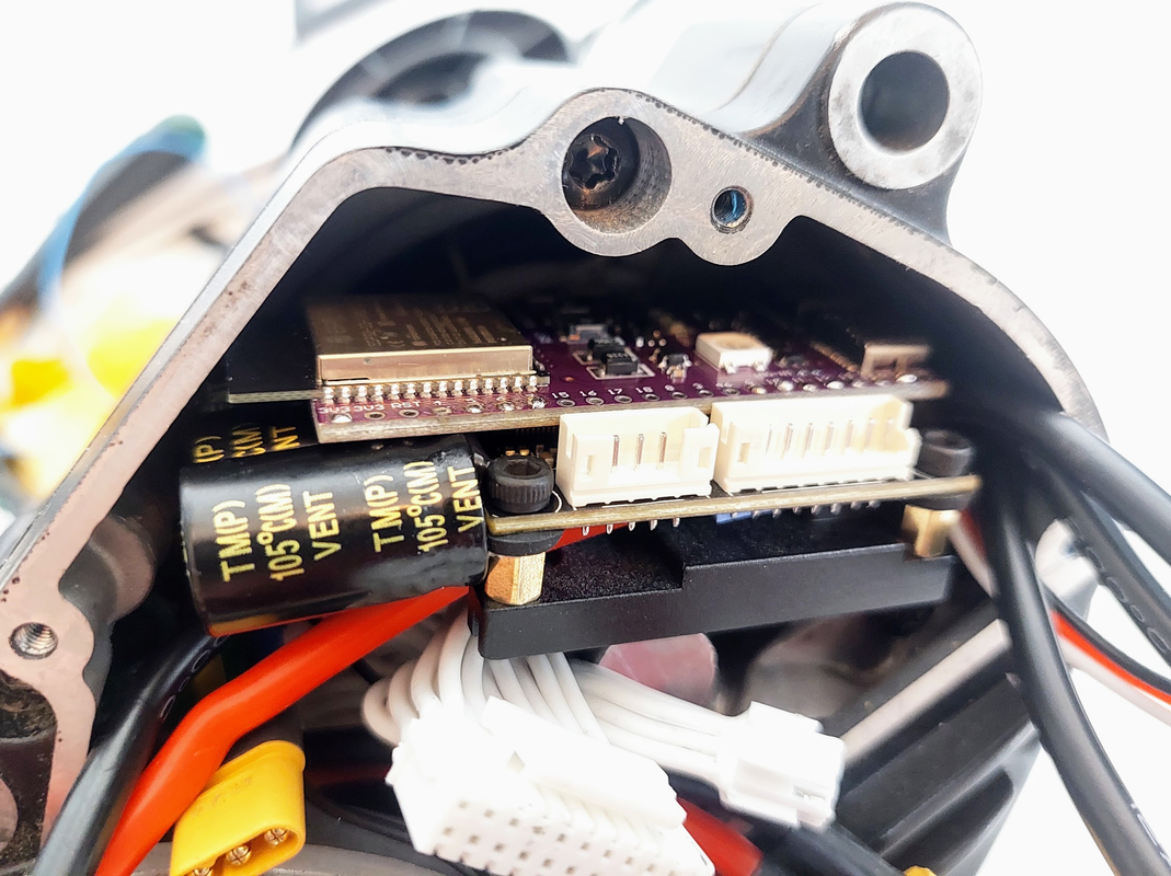
In the same spirit of the DIY display, I am building a DIY EBike electronics. The motor controller is the popular, high performance and OpenSource VESC. Then I add a ESP32-S3 board to run the EBike application, that is also Pyhton code. Again, I can also program the EBike board using wireless, with my phone or PC.

Here is an example of a small VESC that will be installed inside my motor + the EBike board:

Luckily, the ESP32-S3 board I use, can be placed on top of this VESC and the VESC connectors will still be accessible:
Image

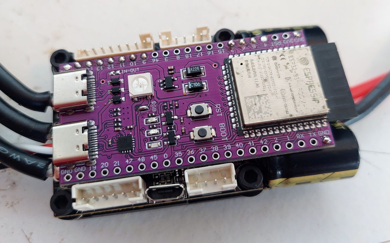
And also, all this are ok to go inside - I just hope wifi will still working with board on that place:
Image
Help me buying tools for my development for Bafang motors - my paypal: casainho [@) gmail.com

Python EBike/EScooter board + VESC, to replace the original EBike/EScooters original motor controller.

Bafang and TSDZ2 EV display: easy to build DIY, Bluetooth and ANT, wireless updates, easy to repair and customize to other EVs.

Developer of OpenSource knowledge and technology for ebikes: OpenSource EV display, Wireless EBike ANT+ and Bluetooth, TSDZ2 / Bafang, KT motor controllers and displays.

whackyfreeware   1 µW

1 µW
Posts: 4
Joined: Sep 30 2022 12:00pm

Re: EasyDIY OpenSource display for EVs: TSDZ2 and Bafang M500/M600 EBike motors

Post by whackyfreeware » Jan 18 2023 5:49pm

Hi y'all,
today I attempted to make Casainho's open source display for the second time (the last one released magic smoke due to sloppy probing around DC-DC converter), after flashing the bootloader I wanted to DFU flash "firmware_ota-TSDZ2-OLED_0.96_I2C-0.20.0.zip" from the NRF connect app, however I didn't get the confirmation or the upload graph like in the case of the last attempt. I tried to connect multiple times to initiate DFU flash again but NRF connect couldn't find my NRF52. I also wanted to flash a fresh bootloader just in case, but openocd couldn't connect to the target, wanting to move on I thought that maybe the firmware was flashed successfully nevertheless.

However after I finished assembly I powered the board up from 12V 1A power supply (In place of Battery_VIN), I was met with black screen and no sign of life from the NRF52 (none that I could measure). Later I tried to power on the NRF52 only, to try to flash a new bootloader but without success.

I think that the initial failure to finish DFU flash was due to my previous power supply which consisted of 2x 9V batteries in series (I thought that for a quick test and flash it will be fine), and they couldn't supply enough current. Or maybe my cheap 0,96" OLED has some weird driver (I already ordered, a 1.3" OLED to test).

I searched for some answers on other forums, but couldn't find anything relevant enough, I will dig some more tho.

I will be very thankful for any suggestions.

whackyfreeware   1 µW

1 µW
Posts: 4
Joined: Sep 30 2022 12:00pm

Re: EasyDIY OpenSource display for EVs: TSDZ2 and Bafang M500/M600 EBike motors

Post by whackyfreeware » Jan 18 2023 6:42pm

martinn27 wrote:
Jan 17 2023 2:34am
Hello everyone, I need your help. I studied in detail the instructions on how to build this display, but I can't flash the bootloader with stlink v2 (V2.J40.S7)
I suspect that I can't get in because "Warn : target nrf52.cpu examination failed"
nrf52840 (PCA10059 , 2.1.0 , 2022.9)
I also don't know how to proceed with telnet communication and whether stlink v2 needs to be modified or is it enough if I have stock firmware
Hey Martin27,
I don't know if I will be of much help, because I faced a similar issue like you, both on linux and windows, however I finally resolved it on linux. In case it is useful to somebody I will list what helped me:

Linux Mint 20
Don't install openocd from apt (at least on linuxmint) it is a version from 2017.
-instead pull the most recent one from github in to the exp. "~/" directory
-go into the newly created directory in terminal: "cd /openocd"
-"./bootstrap"
-"./configure --prefix=/Your-path/openocd-git_install --enable-aice --enable-amtjtagaccel --enable-armjtagew --enable-cmsis-dap --enable-dummy --enable-ftdi --enable-gw16012 --enable-jlink --enable-jtag_vpi --enable-opendous --enable-openjtag_ftdi --enable-osbdm --enable-legacy-ft2232_libftdi --enable-parport --disable-parport-ppdev --enable-parport-giveio --enable-presto_libftdi --enable-remote-bitbang --enable-rlink --enable-stlink --enable-ti-icdi --enable-ulink --enable-usb-blaster-2 --enable-usb_blaster_libftdi --enable-usbprog --enable-vsllink"
-"make"
-"make install"
-if you encounter any errors like: "configure: error: libjaylink-0.2 is required for the SEGGER J-Link Programmer" or "configure: error: hidapi is required for the CMSIS-DAP Compliant Debugger"
-clone them as well: "git clone https://gitlab.zapb.de/libjaylink/libjaylink.git", "sudo apt install libhidapi-dev",
-libjaylink: "cd" (go to home directory), "cd libjaylink/" (go into newly created libjaylink directory), "./autogen.sh", "./configure", "make", "make install"
-hidapi: sudo apt install libhidapi-dev

Congratulations!!! you just installed the newest openocd version! Now of to the flashing the board.

-go to the home directory "cd"
-go to the openocd directory "cd /openocd"
-sudo openocd -f tcl/interface/stlink-dap.cfg -f tcl/target/nrf52.cfg
-You are connected if you get something like this:

Code: Select all

Open On-Chip Debugger 0.12.0+dev-00040-gcda39f929 (2023-01-16-15:51)
Licensed under GNU GPL v2
For bug reports, read
	http://openocd.org/doc/doxygen/bugs.html
Info : auto-selecting first available session transport "dapdirect_swd". To override use 'transport select <transport>'.
Info : Listening on port 6666 for tcl connections
Info : Listening on port 4444 for telnet connections
Info : STLINK V2J29S7 (API v2) VID:PID 0483:3748
Info : Target voltage: 2.490828
Info : Unable to match requested speed 1000 kHz, using 950 kHz
Info : clock speed 950 kHz
Info : stlink_dap_op_connect(connect)
Info : SWD DPIDR 0x2ba01477
-now open new terminal window (ctrl+alt+t) and type:
-"sudo telnet localhost 4444"
-"reset init"
-"nrf52_recover"
-"halt"
-"nrf52.dap apreg 1 0x04 0x01"
-"nrf5 mass_erase"
-"program replace_with_directory_to/bootloader.hex verify"
-"reset exit"
-"exit"

Example of bootloader location: "Downloads/bootloader.hex"
Link to bootloader.hex: https://github.com/OpenSourceEBike/ev_d ... t/releases (scroll down and open oldest release)
Congratulations!!! Now you should be a proud owner of freshly flashed NRF52, of to soldering...

Take these tips with a huge grain of salt, what I just wrote is just a compilation of many forum post all around the internet and an effect of 4hrs of work of an maniac high on solder fumes. Also please excuse any errors and form I wrote, make yourself welcome to correct any of my inaccuracies and mistakes.

That being said I hope that I could at least steer somebody to solution that they need,
Cheers!

Post Reply