Steampunk Voltmeter?

Drunkskunk

100 GW
Joined
Apr 14, 2007
Messages
7,244
Location
Dallas, Texas. U.S.A.
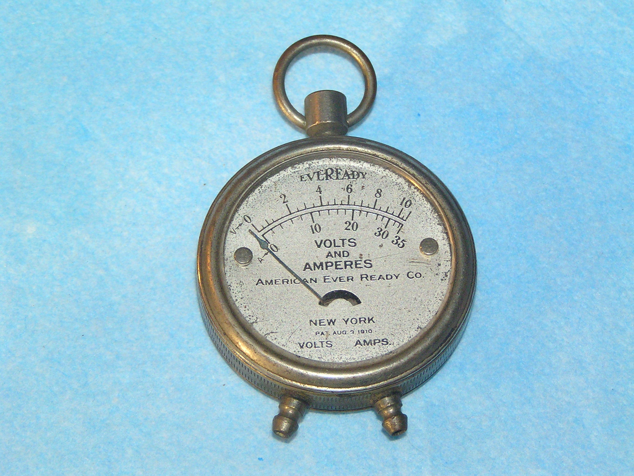
So I picked up a 100 year old volt meter to use as a battery gauge on my steampunk bike, and I have a few questions someone here might know the answer to.

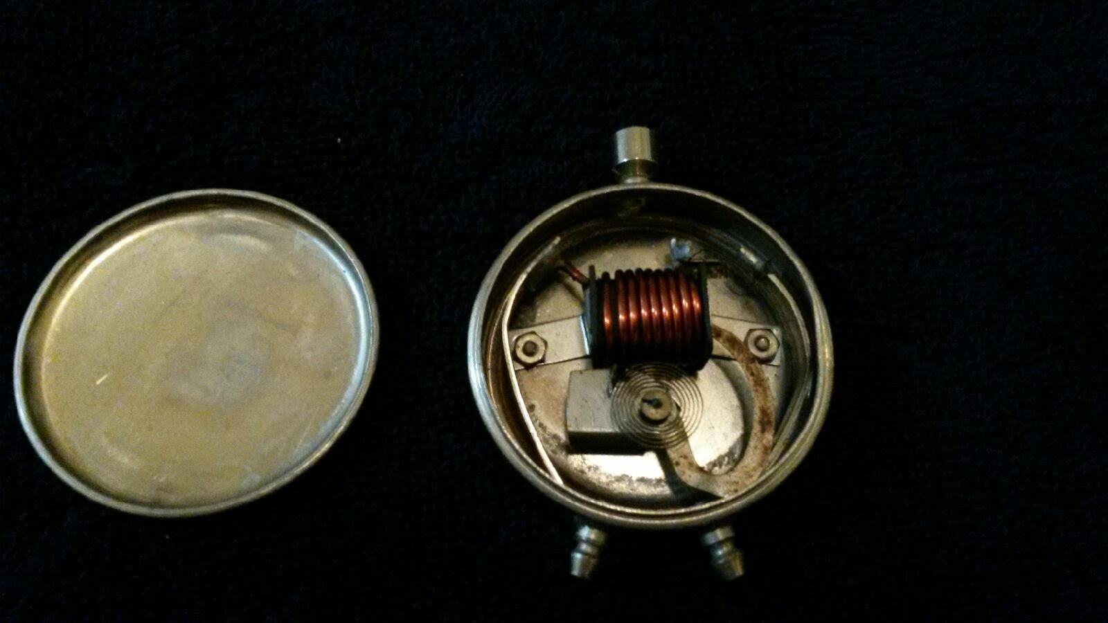
The case is a pocket watch style case, with no obvious seams. I need to get it open, as it seems to stick. I also need to modify it a little. Anyone know how?

The other problem I have right now is offsetting the voltage range for this to work. My bike runs 12s, so 50.4v full charged, and about dead at 40v. That's a ~10 volt sweep, and this is a 10 volt gauge. Perfect. Except I need to ignore 40 volts. I can build a Zener diode circuit to cut off 40 volts, but the amp draw would be higher than I want. Any one have suggestions on a low power circuit that can read volt for volt at 40 to 50 volts?


SaKXg5J.jpg
 
Have you tried unscrewing the back of the case, like you would a watch back? Maybe use an inner tube to develop grip against the metal surface while twisting with the perimeter features.

That is a super cool gauge. I thought the 1960 airplane +/- ammeter I used on a stationary generator bike was hip, but your voltmeter is amazing.
 
The open view of the meter shows it will not work like a typical voltmeter. It's more of an ammeter. If the heavy copper wire coil was replaced with a zillion turns of much smaller wire, then it might function as a voltmeter.

You can make an expanded scale voltmeter by using a zener diode as you suggested. I've done it several times. The meter movement does not take much current, so a small zener works and I put a trimmer pot divider across the meter to make it adjustable for calibration. The zener determines the low end of the meter and the resistor divider gets adjusted for the high end.
 
The opened gauge is indeed an Ammeter measuring current, as the face indicates. The current flows through the coil of green wire and the resulting magnetic field pulls the curved bar into the coil. The bar rotates around an axle that carries the indicating hand on the face side. The force of the magnetic field on the bar is counter-acted by the coiled spring.

If you have some basic understanding of microcontrollers, you could remove the 'guts' of the instrument, attach the hand of the instrument to a small stepper motor and operate the instrument like all modern analog gauges do.
[youtube]https://www.youtube.com/watch?v=F_jcHfDB60o[/youtube].
That would also allow you to display other parameters like miles remaining.

The other option is to rewind the copper coil and adjust offset and gain as fechter suggested. I would probably add a switch to take short readings rather than have the constant drain of the instrument on the battery.

I am curious how the combined Volt and Ammeter from the first post looks on the inside. You may have the fine coil already in there since that instrument was designed to measure Voltage.
 
Going by the face values this looks like a pocket load tester of some sort... kind of like that thing the auto parts store uses to check your car battery. As most of us might know, resting voltage isn't a good indicator of a battery's health or charge. Apply a load to it with known resistance and measure the amps (and also volts in this case) and you'll have a good indication of a cell's health.

It looks like it was sized for smaller scale testing, but 35 amps is quite a current! I wonder what type of battery it was used on. Going off the scales it looks like the resistor inside has a value of between .31 and .33 ohms.

Interesting! I've been thinking of how to include a small steampunk twist on my cruiser build, but I doubt I'll come across a gauge this cool!
 
Lol, it's quite possibly being put to the same use as it was originally intended for :mrgreen: In the early days of motoring EVs often outsold oil burning vehicles and that meters range will be pretty close to EVs of that time.
 
NYC had a whole fleet of Electric Vehicles for taxi's, but with the advent of cheap, mass produced cages and BIG oil, EV's left for a long long time.


stan.distortion said:
In the early days of motoring EVs often outsold oil burning vehicles and that meters range will be pretty close to EVs of that time.
 
Wow I had no idea, and probably wouldn't have thought to look. There's a combo one i really like, but it's shattered. Thanks for the look!
 
I got the back off, It's just press fit. Pic below. It's hard to tell from my shot, but there is a second thin wire coil wrapped under the heavy copper coil that works for the volt meter on this dual meter version.
Now the down side. The volt meter pulls .35 amps at 10 volts. So about 2.8Ω. That makes sense for this thing's intended use. Before WW1, the only common home use of batteries was in cars and radios. Those both used big cells that needed a load put on them to get an accurate voltage reading.

But considering a Zener diode circuit is less than efficient, I'll probably be pulling close to .5 amps to make this work. That's 10% of my battery capacity lost every hour.

Plan B right now is to strip the guts out of this thing and add the movement from a modern small form volt meter, and run it off an Arduino. If I do that, I could and a shunt, and get amps as well


TjFTpay.jpg
 
Drunkskunk said:
I got the back off, It's just press fit. Pic below. It's hard to tell from my shot, but there is a second thin wire coil wrapped under the heavy copper coil that works for the volt meter on this dual meter version.
Now the down side. The volt meter pulls .35 amps at 10 volts. So about 2.8Ω. That makes sense for this thing's intended use. Before WW1, the only common home use of batteries was in cars and radios. Those both used big cells that needed a load put on them to get an accurate voltage reading.

But considering a Zener diode circuit is less than efficient, I'll probably be pulling close to .5 amps to make this work. That's 10% of my battery capacity lost every hour.

Plan B right now is to strip the guts out of this thing and add the movement from a modern small form volt meter, and run it off an Arduino. If I do that, I could and a shunt, and get amps as well


TjFTpay.jpg

As expected, a fine wire for the Voltmeter.

If you already tear this thing apart and get an Arduino involved, you might as well go with a stepper movement. Check out the link in my previous post.
 
Drunkskunk said:
Plan B right now is to strip the guts out of this thing and add the movement from a modern small form volt meter, and run it off an Arduino. If I do that, I could and a shunt, and get amps as well

My late two cents. I think it would be a shame to take this away from original if it means that you can't put it back to its original design with the original parts. That's assuming that these aren't common. If they are common, then no big deal.
 
alpine44 said:
If you have some basic understanding of microcontrollers, you could remove the 'guts' of the instrument, attach the hand of the instrument to a small stepper motor and operate the instrument like all modern analog gauges do.

This idea got me thinking. and after exploring the idea a bit, a stepper motor wouldn't work as it has no positioning sensor and high holding current. If I add a positioning sensor to it, then use gears and a normal motor so it has high holding torque with low current, I'd have a servo. The idea evolved into using a small servo instead.
So on my bench top I have an Arduino nano and a 1.5 gram nano servo the size of a Nickle. It works so far on a bench power supply. with a 680K/51k ohm voltage divider as a sensor. I just need to find a higher efficiency DC/DC converter that will also fit in this thing. So far anything small enough is a power hog. My goal is 0.02 amps or less total.

Hard to get the scale of this thing from the pic. my phone can't focus on something this small, so here's a random internet pic
sm-os1800-lt_500.jpg


wturber said:
My late two cents. I think it would be a shame to take this away from original if it means that you can't put it back to its original design with the original parts. That's assuming that these aren't common. If they are common, then no big deal.

I'd save it if it was rare, but apparently these things were in every home 100 years ago. It's fairly ubiquitous. And now after 100 year's it's going to be useful again.
 
Back
Top