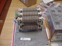
Help needed building dummy load device

rg12

100 kW
Joined
Jul 26, 2014
Messages
1,591
Hey Guys,

I researched the dummy load thing a bit and thought about buying two 500w resistors from eBay to build a 1000w dummy load.
About the cooling solution for the resistors, I will look into it but the main issue now is:

1. What does the ohm do for my use? I know that I want a 1000w dummy load but have no idea what to choose for ohm.
2. How do I connect them? series? parallel? also heard about both...got a little confused.
3. Why do people build dummy load devices from hundreds of little resistors instead of buying a single big one for the wattage they need?
4. How do I connect a pot (and which pot ohm range) to this setup to control the load?


Roy
 
have a look at this

http://www.ebikes.ca/load-resistor-6-8.html
 
Thanks, I have seen those but they can't be controlled...I want to have a pot to control the amp draw
 
You could use a bank of incandescent light bulbs as a load, and vary the load by adding or removing bulbs.
 
I have seen people using switched to engage more or less resistors but it's much more convenient to have a pot to specifically choose a certain amp draw using a digital watt meter to read the amp draw and voltage.
The question is, where do I connected the pot and which kind of pot?
Also the whole ohm thing confuses me...which resistor ohm do I need for my application?
 
V=IR

If you know your voltage, and how much current (I, in amps) you want to push through, then you use those values to compute R (ohms).
 
Sorry but I don't understand even those simple formulas...
Can you give an example?
How would that help me choose the right resistor value? and will it help me know how to add and where to add a pot to control the amp draw? I'm confused...
 
You can't add a pot to vary the power to the load. You could, but because the pot needs to handle the entirety of the power being dumped into the load it would be a huge and expensive pot.

Otherwise you'd need something like a brushed motor controller to vary the power.

This is why most people used a load of fixed resistance, or something they can vary manually by adding/removing bulbs, using different tappings on resistors etc.

If you want you load to dissipate 1000W then you also need to know how many amps or volts that's at.

If it's a 50V battery then 1000W/50V = 20A

R = V/I = 50/20 = 2.5 ohms
 
correct. you need to know FIRST which load you need. you can't vary it "on the fly". at least not with a resistor network.
basically they are very simple, but you still you need to know electrotechnical basic knowledge.

the most important one is OHM's law.

U = I * R meaning: voltage [V] = current [A] * resistance [R] and
P = U * I meaning: power [W] = voltage [V] * current [A]

with these two formulas you can calculate the TOTAL resistance needed.

you then need two other formulas, one for resistors in series, and one in parallel:

if you put them in series: R(total) = R1 + R2 + R3 .... + Rx
if you put them in parallel: R(total) = R1 * R2 / (R1 + R2)

hope that makes sense to you
 
Ok I think I got it so it will be a problem pulling constant current since the voltage drops when the battery capacity is drained...
How is it possible to control the load with a brushed dc controller?
 
rg12 said:
Ok I think I got it so it will be a problem pulling constant current since the voltage drops when the battery capacity is drained...
How is it possible to control the load with a brushed dc controller?
yes. the total power consumed will decrease as voltage decreases.
you just use a controller and connect the load to the output. then you can connect a throttle to the controller and control the load.
the question is: why do you need a constant load? what do you try to acchieve?
 
izeman said:
rg12 said:
Ok I think I got it so it will be a problem pulling constant current since the voltage drops when the battery capacity is drained...
How is it possible to control the load with a brushed dc controller?
yes. the total power consumed will decrease as voltage decreases.
you just use a controller and connect the load to the output. then you can connect a throttle to the controller and control the load.
the question is: why do you need a constant load? what do you try to acchieve?

I want to measure voltage sag under different loads on different lithium chemistries and some other basic tests.

So I can take a DC controller and connect the resistor dummy load to the load side, thats awesome but the question remains, how many ohms should I use? I want to use different battery voltages.
Also, will the amp draw stay constant? not talking about wattage that will change because the voltage of the battery drops because of loss of capacity...
I need for example to have a full hour of constant 20A draw. will I achieve that with a DC controller? would the amp draw change when the resistors heat up?
 
thanks for explaining. but i still don't see what you want to acchieve? what is your goal?
why do you need to measure voltage sag? just to know the SOC of a special chemistry under a specific load? is this a science project, or what is the "real world value"?
maybe i will explain what i did: i built a 600w discharger module to determine internal resistance of my rc lipo packs. those are 6s packs with 23v nominal voltage. so i connected the 600w 6ohm resistor through an inrush limiter switch. this gave me a current of around 25v. but this load was only applied for 10s. so i wrote down the no load voltage, turned on the load, waited 10s and noted down the sag, while reading the current at this moment. using ohm's law this gave me internal resistance.
i can also use this resistor to bring down a full pack to storage voltage in a few minutes. https://endless-sphere.com/forums/viewtopic.php?f=1&t=84372#p1235514

if you want to use a motor controller to control discharge current you will also need something like a cycle analyst. the cycle anaylist will read the current in real time, and adjust the throttle accordingly. so it's a quite pricey setup. a dc controller works completely different from a bldc controller. a dc controller adjusts the voltage going to the load from 0v up to battery supply voltage. i'm not sure this is what you want. if you take a regular ebike controller and connect an ohm's load between each of the three phases, then this will be your total load. so let's say you have 3x 500w resistors (or 3 resistor network made of smaller resistors) and a controller capable of delivering 1500w then you should be fine. in theory. i never tried it. if i did, then i would calculate resistance based on full voltage. so in the case above: 50v and a 500w resistor would give you 10A per phase therefore 5ohm per resistor.
but as i said: i never tried that. maybe your controller will just blow up instantly *ggg*
 
I want to use it to measure internal resistance, discharge packs just like you said but I'm not going to work with a fixed pack voltage, I want it to work with any voltage up to 100v.
It sucks that the dc controller knob doesn't change the current but changes the voltage.
are you sure about that? because BLDC controllers use the pack's voltage and change the current depending on throttle position.
I don't need a CA, I can use a simple watt meter to measure amps, watts, voltage, Ah etc...
 
You will need the CA to limit the current from/to the controller.
For internal resistance measurement you don't need the load for minutes. 10s is more than enough. Read my thread. Many people write clever stuff about internal resistance measurement.
I suggest you build yourself a network of resistors with interconnections than can easily be changed. So you can build the needed resistor on tjr the fly.
 
The internal resistance measurement is just a bonus, it's more for discharging big battery packs...
A cycle analyst is too expensive for this project.
It gets very complex if I want to have different amp numbers for a single voltage.
It seems that if I want to have 20A draw for 72v 60v and 48v that I will need 3 different dummy load devices built from different resistors...

btw, if I connect an 84v battery for discharge on a 1000w resistor, while the voltage is dropping (not due to sag but due to capacity depleting), will the amps be raised automatically in order to stay at a 1000w or will it drop below 1000w? I mean, are the amps constant?
 
rg12 said:
It seems that if I want to have 20A draw for 72v 60v and 48v that I will need 3 different dummy load devices built from different resistors...

That's why I suggested a bunch of plain old fashioned light bulbs with parallel wired sockets. You can easily characterize the resistance of a single bulb, and simply divide the ohm value of one bulb by the number of bulbs you screw down. I think it may be the only way to do what you're talking about at much less than the cost of a Cycle Analyst.

A light bulb is not only a precision resistor; it's one that radiates out most of its waste heat so you don't have to do anything special to keep it from overheating
 
Light bulbs - You using 12V bulbs or regular house hold bulbs?

What about using a stove top element coil, hopefully you can find some discarded so you get them for free.

There was a guru here that posted using a heating element, think it was the guy from Quebec, his E.S. handle completely escapes me right now.
 
I have been exploring dummy loads which are capable of handling ebike levels of power as well. The commercial units which do what you want get pretty expensive. The most promising I have seen is http://www.westmountainradio.com/cba.php.

Most people who do casual testing end up using a bank of light bulbs or power resistors which they manually control with switches. It is quick and dirty, but it get you in the right ball park.
 
markz said:
Light bulbs - You using 12V bulbs or regular house hold bulbs?

I've used regular old 120V bulbs for resistive load banks before. They don't even have to glow-- there's still a very consistent resistance. At 36V and up, though, they'll do something to let you know the juice is moving.

A 100W bulb draws 0.8A at 120V, so you need a mess of them to pull 20A at lower voltage. Higher wattage bulbs tend to cost more per watt, though. And the cheapest sockets sometimes have restrictive wattage limits. Automotive or other 12V bulbs might be better for adding up to the desired amp loads, but it seems like they'd cost more overall. And the wiring would be more complex than a simple all-parallel arrangement.

Salvaged heating elements would be capable of discharging at high current, but with much less adjustability.
 
White kind of bulbs can I use for dc voltages ranging from 40v to 90v?
 
I use a collection of 100W , 24v minature halogen bulbs ....(thats ~6 ohm each)
Very handy at our voltage/current levels, and compact too.
bought 10 for $5 off Ebay
Like these ...but much cheaper !
http://www.ebay.com.au/itm/PLATINUM-64638-100W-24V-HALOGEN-BULB-/141901613905?hash=item2109fecb51:g:Q8UAAOSwWTRWvR9X
 
rg12 said:
White kind of bulbs can I use for dc voltages ranging from 40v to 90v?

Any voltage incandescent bulb will do. If the bulb's voltage is below 90V, you have to put two or more in series to get the per-bulb voltage at or below its rating. (So you wouldn't want to use 3V bulbs, for instance, which would require at least 30 bulbs on each series.) The advantage of using bulbs with higher voltage, like 120V, is that you can wire all of them in parallel. Then it's only a matter of screwing in or unscrewing them until you have the total resistance/power you want.
 
Back
Top