DC to DC converter have 3 wires for 48V+

Joined
Feb 26, 2018
Messages
154
Why does my DC to DC converter seem to have 3 wires for 48V+?
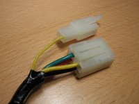
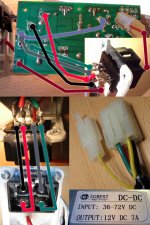
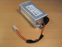
It has a connect with 4 wires (green, red, yellow, black) and a separate connect with red.

Seems like green (-) and red (48V+) is always connected to the battery.
And yellow gives 48V+ when ignition is ON.
Black is 12V+ when ignition is ON.
And red in separate connector gives 48V+ when ignition is ON.

Red in separate connector seems to only supply the controller. So called "Power Supply for Digital stage of Controller" in the manual with a thin wire so not the power for the motor, just the electronic chips and stuff in the controller guess.
Is this because the controller needs a more stable 48V+ so it have its own supply that is not used by anything else?
Or why does the controller have multiple wires with 48V+?

More pictures: https://scootergrisen.org/forum/viewtopic.php?f=3&t=3602
2.jpg
1.jpg
 
Not a lot to go on here, but my guess is that the yellow wire is switched by the ignition to activate the converter. Some controllers (Sabvoton, ASI BAC) have low-current battery-level inputs to enable the controller, so that's probably what the red is. This prevents operation of the vehicle when the ignition isn't switched, without having to disconnect the battery all the time.

Photos, wiring diagrams, controller and converter model and specs, etc. might help to clarify further.
 
Ok so i guess it makes sense to only give 48V+ to the controller when the ignition is OFF so that any recidual power inside the DC to DC converter cant be used to run the scooter after it is suppose to be OFF.

But are you even sure this happens?

If the battery have just been connected and i turn OFF and then disconnect the battery and turn ON then the recidual power inside the DC to DC converter can power such things as the display and the front light for a few seconds.

Not sure if the same is the case for the wire to the controller i have not measures it yet.

But why use a seperate low current wire from the DC to DC converter.
Why not use the yellow wire for the controller that is also disconnected when OFF?
 
scootergrisen said:
Ok so i guess it makes sense to only give 48V+ to the controller when the ignition is OFF so that any recidual power inside the DC to DC converter cant be used to run the scooter after it is suppose to be OFF.
If the controller is connected to the battery, and there is no "enable" line, then twisting the throttle (which is powered by the controller) will cause the scooter to go, regardless of whether the scooter is "on".

If the battery have just been connected and i turn OFF and then disconnect the battery and turn ON then the recidual power inside the DC to DC converter can power such things as the display and the front light for a few seconds.

But why use a seperate low current wire from the DC to DC converter.
Why not use the yellow wire for the controller that is also disconnected when OFF?
How are the outside wires connected to the inside wires? Is it red-red, green-green, black-black, yellow-gray? If so, then it looks like the yellow is connected to the single red via the very simple and cheap protection of a giant resistor. Looks like a 10 ohm, probably rated for a few watts, not sure. If the red wire is connected normally and is only drawing, say, 10-100 mA, then the resistor doesn't drop much voltage and doesn't heat up much. But if the red is inadvertently shorted to ground, it will draw 5 A until the resistor burns up, rather than drawing much more and damaging some more valuable piece of equipment.

So you can think of the single red as being connected directly to the yellow in normal operation, with some protection if it is miswired. Thus when you disconnect yellow using the keyswitch, this immediately disconnects red from controller enable, so the residual charge in the converter caps is irrelevant. This charge only affects the 12 V output.
 
I have not tested what color wire on the inside goes to what color wire on the outside.
Next time i take it apart i can take more pictures.

What is the point of having red (48v+) always connected to the battery and then yellow (48v+) only when ignition is ON?
Why not just only give the DC to DC converter 48v+ when the ignition is ON?
Would that give to much current through the ignition?
Or maybe it will cause to much sparking inside the ignition?

I have noticed two times if i connect the big connector with the 4 wires to the DC to DC converter a spark is created and quite a big sound. I am guessing this might happens if the DC to DC converter is discharged and goes from 0 to 48v+ quickly.
 
For 90% of the cheap Chinese DC-DC converters out there, they all seem to follow the same pattern:

  • Red is 48V power (in)
  • Yellow is 12V power (out)
  • Black is common ground (i.e. ground for both 48V and 12V)

If you want it on all the time, just wire the red up to your battery.
If you want it on some of the time, then just add a high-voltage switch to the red power circuit.

Michael

P.S. how this maps to your particular situation is not clear -- I merely provide this for comparison.

P.P.S. I have two of these (https://www.ebay.com/itm/Pro-Chaser...ulator-Step-Down-to-12V-180W-15A/223130946668) on my 72V bike: one to power a set of VERY LOUD dual-tone automobile-style horns + some accessories, and the other for the rest of the system.
 
scootergrisen said:
What is the point of having red (48v+) always connected to the battery and then yellow (48v+) only when ignition is ON?
Why not just only give the DC to DC converter 48v+ when the ignition is ON?
Would that give to much current through the ignition?
Or maybe it will cause to much sparking inside the ignition?
You're on the right track. The converter has large capacitors at its input to smooth the power flow. If the unit has been disconnected and the caps are discharged, then the next time you connect it there will be a large inrush of current as the capacitors charge. If you do this by connecting a switch or plugging in the plug, then all that current will pass through the first small point that makes contact, resulting in local melting, smoke, light, noise, etc. It seems dramatic, but the only real damage it causes is oxidation of the switch or connector. Over time, this oxidation will start to affect the quality of the connection.

It's best to switch a connection like this with a solid-state switch, and leave the battery connected all the time. In your case, it looks like the yellow wire activates this switching in the converter, in addition to providing a controller enable signal via the red wire.
 
I managed to figure out which wire on the inside goes to what wire on the outside.
The only wire color that is consistent on both sides are the red wire.

Seems like the fat yellow wire sends 48V+ into the converter (when ignition is ON) and then it goes back out the thin yellow wire through the big 10 Ohm resistor.
From the description above it sounds like the resistor is being used like a fuse.

dc_til_dc_konverter_24.jpg
 
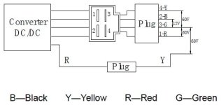
I found this diagram in a service manual.
I guess "60V" could be anything from "36V" to "72V" depending on what battery voltage is used.
dcdcdiagram.jpg
 
Back
Top