Conversion Honda motorcycle to electric 96v - 8000w hubmotor - 6.3kWh

Lightrule

1 mW
Joined
Oct 20, 2019
Messages
15
Hey all, I'm new to this forum :) I'm about to start a conversion project with the help of a colleague from work. We're about to electrify an old Honda CB1 motorcycle (or CB400F in other markets). The main purpose of the motorcycle is for driving the distance between my hometown Zwolle (the Netherlands) and the eastern part of the country, which is where my parents and girlfriend live. I'm going to use the motorcycle only on days where conditions are "good" i.e. not too cold and no rain / wet roads. As to the 'why' of the project: I'm stoked about electric vehicles and I've got a passion for riding motorcycles. These two combined along with the desire to learn more about the underlying technology of EV's is why I'm doing this!

As for a little bit more on my background: I'm 29 years old with an engineering degree in logistics. I didn't have any meaningful experience with electrical systems before I started researching relevant topics for this project but thanks to the help of a colleague (who's an electrical engineer) and raw dedication I'm feeling confident this project will be a success!

So here is what I have in mind for the motorcycle requirements:

Required range
64 kilometers (40 miles) minimum. I'll be driving on roads with mainly 80 km/h speed limit so I guess my average speed will be around 60 km/h on the above mentioned route.

Required top speed
90 km/h (56 mph) to overtake any slow vehicles (faster is bonus)

Required acceleration
0 - 90 km/h (0 - 56 mph) in 10-13 seconds (quicker is bonus)

Charging
Since the motorcycle won't be for making long distance trips (I'm building it mainly for a specific route) I decided to go with the slow charging option (regular 220v 15A socket at home).

Weight
Haven't calculated the exact weight yet but I'm thinking the electric motorcycle (including myself driving it) will weigh around 250 kilos (or 551 lbs).

To achieve these requirements I'm planning on using the following components:

Donor bike
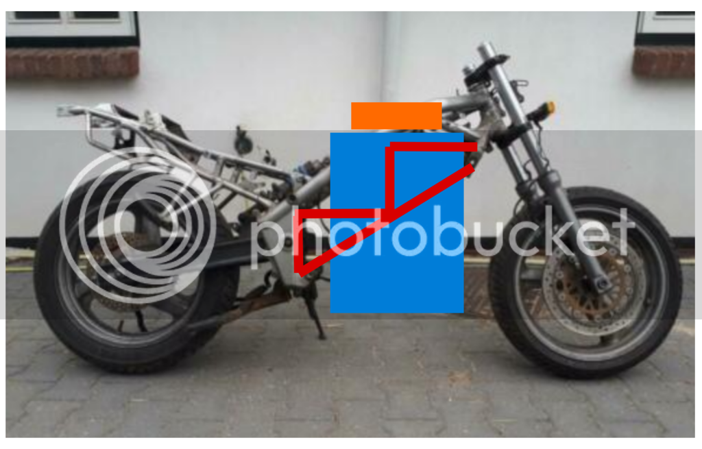
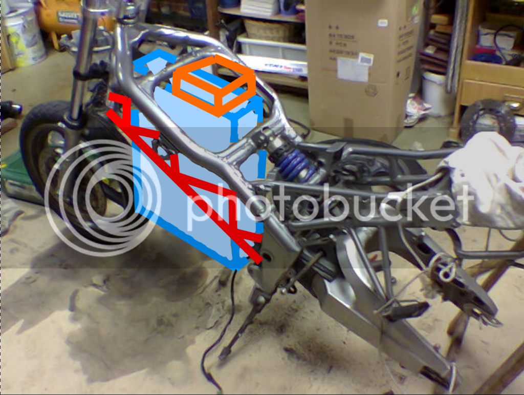
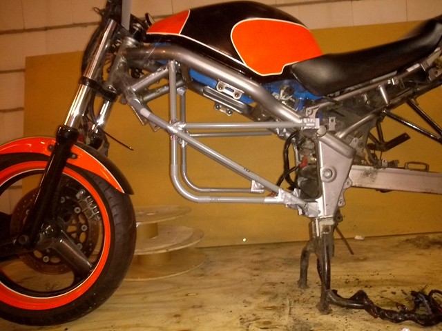
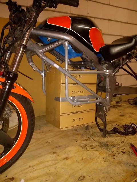
Honda CB1 (or CB400F) from 1991. I'll add some pictures of it in the next post. I chose this bike because of the "open" frame which creates lots of space for the EV-components when the engine block is removed. Also it's a 400cc bike so it's probably lightweight (frame wise). Plus the colors, I love them! :)

Hubmotor
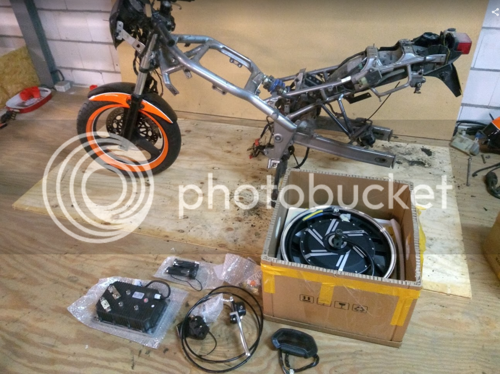
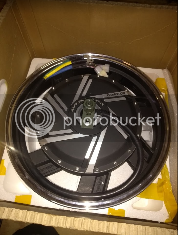
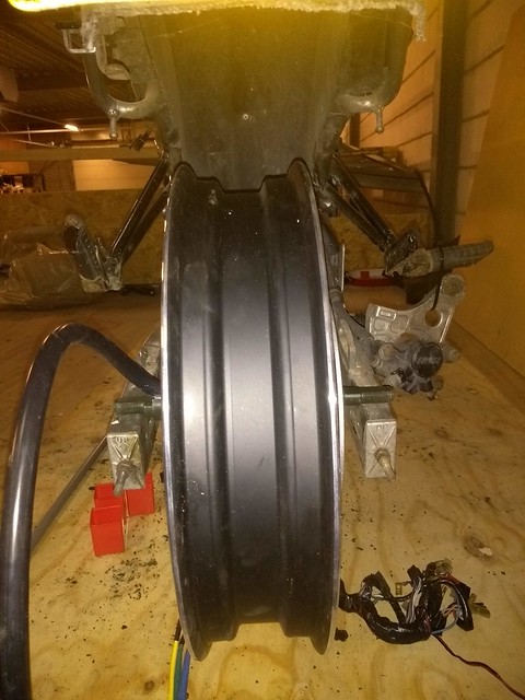
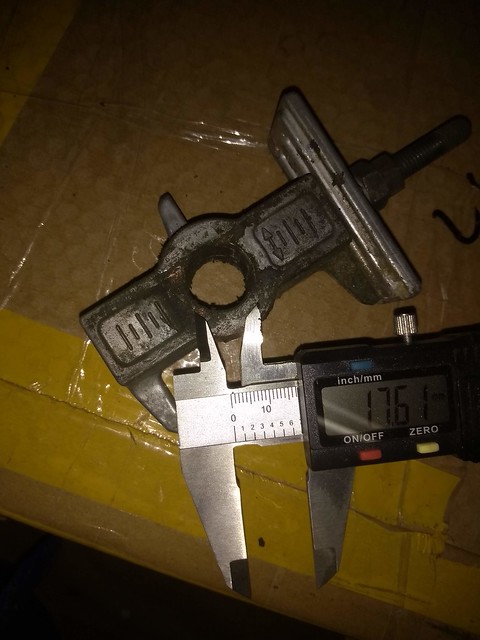
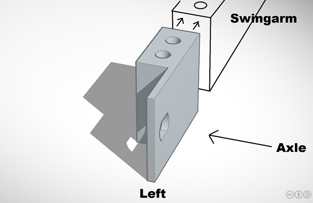
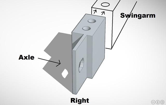
QS Motor 8000w rated hubmotor (16000watt peak according to their website) 17 inch. I hope the M18 axle it comes with will fit into the swingarm but I doubt it. This will probably require some machining (which I'll be outsourcing since I don't have any large machines myself).

Battery
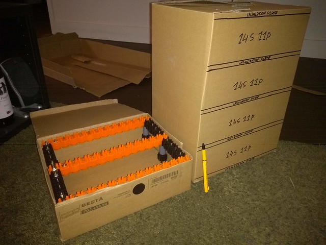
6,2kWh (or thereabouts) made from lithium-ion 18650 cells. I already bought 106 pieces of new LG INR18650-M29 2850mAh - 10A cells to create a "temporary" 96V and 26s4p battery to get the motorcycle working (although I'll be limiting the hubmotor load to 1250w to avoid frying the battery). I'm doing it this way to create a working "showcase" of the motorcycle with which I think I can attract financial donations from fellow colleagues and friends. With these donations I'm upgrading the battery to 26s22p. By then I can use the full power of the hubmotor. Also I'll be using the Vruzend v2.1 modular battery kit to assemble the individuals cells into one battery. These are rated for 20A power draw per cell but according to my calculations I'll be drawing less than 10A per cell at peak load, both in the temp battery as well as in the final battery.

For the minium required kWh, I used the following calculation:
69wh * 64km = 4416wh <----- average consumption of energy per kilometer times kilometers of riding
then 4416 * 1.2 = 5299wh <----- since fully discharging the batteries is a bad idea I kept the minimum charge at 20% charge.
I've added another 1000wh (or 1kWh) to the battery by adding additional cells in parallel, otherwise I'd be stressing the cells too much (more than the 10A which they are rated for at peak load).
Together this is about 6.2 or 6.3kwh which should be enough for the 64 kilometers desired range but I guess I'll find that out once I actually attempt the ride for the first time ^^

As for the layout of the final battery (26s22p) I might go with two blocks of 13s22p and connect these in series as to make it easier to fit them into the frame. Any suggestions on this matter this would be super helpful!

Also haven't decided on the battery box yet. I'm thinking of creating a see-through plexiglass encasing (CNC'ed) because I really like the idea of seeing the "insides" of the systems that run the motorcycle. Also the see-through aspect could be helpful for visually checking for faults and for explaining the system to others.

Controller
Kelly Sinosoidal Controller KLS96501-8080HKelly Sinosoidal Controller KLS96501-8080H
This comes with the QS Motors conversion kit I'm planning on buying. It allows regen and is programmable. Also it allows for the nominal and peak amperage the system will produce.

BMS
To be decided. Any help with this would be much appreciated! It's gotta be compatible with both the temp battery (26s4p) and the final battery (26s22p or 2 times 13s22p). I have found some interesting options but I'm not quite sure yet which one to choose. Also some of them come with communications and a main relay but I'm not sure what this is for. It definitely needs to be balancing the cells either individually or per group (parallel) to ensure long battery health. Feel free to enlighten me on this!

DC-DC converter
Not sure yet what to do with this. If I hook up a DC-DC converter from the main 96v battery to power the 12v system on the bike, I'm thinking I might be in trouble when, during the ride, the main system shuts down (for whatever reason) and I'll be left without lights or gauges. Would it be better to create a dedicated 12v battery for this system and charge it separately from the main battery or through the main battery? If anyone could chip in, that'd be awesome!

I'm probably missing half of the required components to get it running but I think these are the main ones. As for how to hook all of this up, that's for finding out once we get all the components together and assembling them in a test-setup. This is also where the knowledge of my colleague is going to be very helpful. After this phase the plan is to add everything to the frame and go for a first test drive.

I'll be updating this page regularly the coming months as the project progresses so stay tuned! All tips and suggestions are super welcome! Thanks!!
 
I will follow this very interesting project.

A few questions if I may:

Is the ICE engine a stressed member that adds rigidity to the frame? If so, will you build a battery box that will be strong enough to act as a stressed member?

How much do you estimate that the QS motor conversion kit will cost including shipping and import taxes?

Will you have it tested and registered at the RDW as an electric motorcycle? How will you comply with all the rules and law? I believe it is very hard and expensive to get through the tests. But if you don't and still ride it you'll be uninsured.

I wish you well and hope you will update this thread with your progress.
 
I hadn't thought of this but apparently the engine is indeed a stressed member of the frame. I guess this means I'll have to weld some metal bars to it to reinforce the frame. I wonder whether it's really necessary though, since the motorcycle isn't exactly going to be a crazy fast machine? If only I knew how much force the frame can endure without the engine acting as a support before it starts affecting the stability of the bike.. maybe it's perfectly suitable to ride without added support until a certain cornering speed and corresponding large forces / stress?

Regarding the cost of the QS Motors conversion kit, I received this message from a QS Motors representative:

8000W 96V 17inch Electric motorcycle Conversion Kits: USD940
Shipping cost by air express: USD206

Total: USD1146


In Euro's this is about 1033,- without import taxes. I'm counting on an added 350,- euro's for the taxes and clearance costs. So a total of around 1400,- euro's. I made contact with Vectore Bike in Germany, QS Motors European dealership. They said they could get the kit for me and then I wouldn't have to pay for taxes and clearance but it would take them 3 months to get it (they said they only receive orders from China once every 2 to 3 months and they're not expecting the next shipment until january next year.. bummer. Good to know though that this is a possibility, for any future purchases ;)

I will have the motorcycle tested at RDW. It's a bit of a gray area for me regarding how much this is going to cost me exacly but I called a while back and they said I need to prepare to fork over 1000,- to get it road legalized. :shock: About the rules and law the bike's going to need to comply to: there's a ton of information on the RDW website.

I'm picking the bike up on october 31st and then stripping it on november 2nd. I'll be posting an update after that. Cheers :)
 
If you are going to get this road legal in the Netherlands then I wish you all the Luck.
I did try the same a few times but had no luck because the people from RDW do not know a lot about conversions to E.
Regulations do a verry grey area discription and are verry wide to explain. Everything must be EU certificate and makes it almost unpossible to get it RL.

Good luck
 
I too suspect it will be very difficult and very expensive to get this through the RDW tests and road legal. And if you do manage to get it done it will probably have cost you as much as a good second hand electric Zero motorcycle. Maybe just wait for the new Sur-Ron Storm Bee motorcycle to come out. If they get it road legal from the factory that will be a very interesting bike!: https://electrek.co/2019/09/22/first-look-sur-ron-storm-bee-electric-motorcycle/
 
Update:

Motorcycle completely stripped of all unnecessary elements. I've kept the original wiring intact. Not sure yet whether to use these or rewire the whole thing.

Ordering the following parts from QS Motors this weekend:

https://nl.aliexpress.com/item/32889432936.html?spm=a2g0z.12010612.8148356.20.333f6b53h3dULF

While I'm waiting for the parts to arrive I'll focus on two things:
1. Designing the frame beams that'll hold the battery (and which act as a support for the whole frame) and getting these beams installed by a third party.
2. Designing and building the temporary battery consisting of LG 18650 cells (26s4p) and Vruzend v2.1 units. This part also include sourcing and installing a suitable BMS which will fit on both the temporary and the final (26s22p) battery.

I'll post some pictures over the weekend.

:thumb:
 
For the frame (in red), the battery pack (in blue) and the controller (in orange), I was thinking the following. Would this type of added frame support be enough to add enough strength? Probably also a lateral structure will be needed.

Capture_zpsyltuod6c.png


Capture2_zpsbhggixqv.png


Let me know your thoughts.

Thanks :thumb:
 
:thumb:
Yes that seems a very smart way to replace the lost strength that the removed engine provided. If you build the battery box/frame out of metal tubes or plate and integrate (welded or bolted) that as well into the total frame structure it will probably stiffen it up even further.

Did you contact the RDW already and ask for info on how to get the bike road legal once completed? If not I would do so to prevent having to change a lot afterwards.

Good luck and enjoy building!
 
Update:

Received the kit from QS Motors in good shape (super fast delivery too, took less than 2 weeks) and great communication with the sales person (Robert Chen). All in all, the order and delivery process at QS Motors is really good imo. Hopefully the quality of the products is equally good.

Knipsel_zpsxend6kiw.png


Knipsel2_zps201uhxgn.png


Knipsel3_zpsyx2cn4uk.png


Not sure what's up with these little wires wrapped in copper. Will investigate later.

Might have some time later this week to try to fit the HUB-motor in the swingarm.
 
Nice project! Those wires are hall sensor wires, two sets in case if you damage one set. You need hall sensors to run that motor smooth
 
When making your tire selection choose the tire that will result in the smallest outside diameter wheel you can. Hubmotors always like the smallest diameter possible for best performance. At highway cruising speeds you'll really chew through battery capacity, so you'll want to work on the aerodynamics. Gassers have so much heat to shed (about 2/3rd of the explosive energy of the gasoline is dissipated to the environment) that the hot parts need to stick out. We don't have that issue, every change you make to reduce wind resistance pays off, whether it's narrowing the handlebars or lowering ride height to punch a smaller hole through the air, or a front fairing to more smoothly punch that hole, or making parts smoother and tapering the tail smoothly to reduce the turbulent wake you pull behind the bike. This last part is the most ignored, but arguably the most important. Before getting too far it would be so easy to splice a tube into the main frame tube to lengthen the wheelbase a bit so you can orient the battery the other way to make it less of a wind dam.

Windy days will have a big impact on range and energy usage for a given speed, so don't let a big headwind day leave you hunting for an outlet part way through the ride, and you'll love a tailwind so you can show off more.

You may be cutting it close on the energy required, so little things like extra pressure in the tires to reduce rolling resistance or drafting other vehicles make more difference with electric.
 
Lightrule said:
For the frame (in red), the battery pack (in blue) and the controller (in orange), I was thinking the following. Would this type of added frame support be enough to add enough strength? Probably also a lateral structure will be needed.

Capture_zpsyltuod6c.png


Capture2_zpsbhggixqv.png


Let me know your thoughts.

Thanks :thumb:
Your frame supports don't need to be that complicated, the long straight Bart from beneath the headstock to the swingarm pivot or bottom point and 2 more bars from both those points to the engine mount mid way up the frame is plenty, making a triangle either side. Then bolt the battery box to and between these and it'll be stiffer than the stock setup. I'd keep them fairly light weight too, perhaps using an oval profile tube to keep it slender.

Looks like a good project.

Sent from my moto g(7) plus using Tapatalk

 
So here comes a long overdue post. Work has been a bit demanding these last few weeks so the project hasn't received the attention I was hoping to give it. Anyway, here's what's new:

49537293323_d8df4226c3_z.jpg

Above: Built a dummy batterybox so I could play around with dimensions and fitting. The plan is to replace the cardboard with a 3D-printed casing made of plastic. The BMS will be added to this setup as well as soon I buy it. So for the battery I'm thinking 96 volt, 62Ah battery consisting of 616 cells (18650). These will be provided through one of the suppliers of the company I work with but have been delayed by the Corona virus. I'm using Vruzend V2.1 modules to connect the cells into a pack.

49537788166_ba7352c36a_z.jpg

Above: Fitting the HUB-motor into the swingarm has proven to be quite the puzzle. I guess I was secretly hoping it would be plug & play with the old Honda setup, using the original spanners (below) but reality was a bit different.

49537293403_c054ee9bc2_z.jpg

Above: The original spanners are just a tad too narrow to fit the axle of the QS motor. I could widen them but then I also run into a bunch of other issues so I'm thinking of cutting a part of the swingarm off and fit custom made suspension-units into it (below).

49538183067_ebb437a283_z.jpg

Above: Left side of swingarm depicted with the suspension-unit sliding into it with 2 holes for bolts to secure it in place.

49537463888_8394d3e788_z.jpg

Above: Right side of swingarm and the suspension unit (made with TinkerCAD).

49537788236_31e753a357_z.jpg

As for the frame support I think I'm settling on this design. Right now it's just made of plastic tubing but it's a good way to get a feel of the structure and its dimensions. Also helps me to check whether the battery box is going to fit (below).

49538013982_9435e5ff5e_z.jpg

Above: The dummy battery box within the frame. Where I've added ducttape on the side of the box that's where I want it to sit on the frame and bolted secure. Ground clearance is about 18 centimers at this point. I might tinker around a bit with the final battery design and placement within the frame to increase the clearance and reduce the surface area / wind resistance.

That's about it for now. I'm hoping to get the suspension-units made soon and fit the motor. Then hook it up to the controller and a smaller battery to give it a test spin.

Cheers :)
 
:thumb:
Smart to use CAD (Cardboard Aided Design) to trial fit the battery box :wink:
Have you already contacted the RDW for this build? Are they a little more forgiving these days to get DIY EV builds tested and road legal? Good luck with the rest of the build and enjoy!
 
Be sure to double check how the axle flats on the motor axle are aligned. Many of the manufacturers of large hubmotors machine those flats on different planes, and that includes the old V1 QS273 motor I bought used back in 2011. When they are on different planes it makes mounting the motor more tricky, and you have to take it into consideration for removal to change the tire.

Also, it looks like you're planning a through-hole type of torque plate to prevent the axle from spinning. I would strongly caution against that, because you can never achieve a tight enough fit that won't loosen and deform over time (or worse if you choose a hard steel, deform the axle). Do no underestimate the forces at the axle flats...we're talking about thousands of pounds of force at that small radius, and the alternating direction of those forces between acceleration and regen braking will make it rock back and forth.

I've built quite a few ebikes using similar motors, and the only way to go is with torque arms or dropouts that use strong bolts to clamp to the axle flats. I clamp to mine so securely that axle nuts are just decoration and often don't even put them on. You can't use aluminum for this job either...steel only and at least 1/2" wide for a bike the size of yours, though personally I'd go with 5/8 or 3/4. If your swingarm is aluminum, that will require special consideration in how you connect what is essentially motor mounts made of steel.

Other motor mounting consideration are:
- water follow wires like the channel of a river, so the wiring harness needs a drip loop below and reward before it enters the motor. That also means orienting the hole where the harness enters so it is down or facing rearward. Sealing that entrance with silicone can help, but it can't overcome the negative pressure resulting inside the motor when it is warm from use and cold rain water hits the aluminum side covers. Justin, our resident ebike scientist demonstrated that this can draw water into a well sealed motor by sucking it through the wiring harness itself, so take care to shield the other end of the wiring harness from rain and road spray.
- The axle flats are the weakest point of any hubmotor drive, because not only does the axle see the full force of the emoto weight on that wheel and any impacts from holes and bumps, but all of the spinning force to drive the emoto. Add to that the Chinese still haven't learned that it would be far stronger to put a radius in the corner where the axle flat starts instead of a sharp 90° cut. That transition point from where the axle is full round to the axle flats focuses the stresses there and metal fatigue sets in with numerous examples on the forum of axle failures exactly there. The axle is strongest with the axle flats oriented vertically, and as long as you take extra care to align the wheel perfectly before any welding it works fine. That also makes it easier to spread the load on the axle from weight and road impacts along the length of the axle.
 
Nice build here.

Can I just check something in the last post here about mounting the hub motor with the axle flats vertical rather than horizontal. I see majority of the torque plates being used inline with the swing arm (where they are often just bolted through) with the axle flats horizontal.

Are you saying the adaptor plates for this build should have the flats vertical so the axle flat cut out rotated 90 degrees looking at the CAD drawings?

I’ve done the same with my Aprilia conversion that is still underway (same QS Motor) but this was out of necessity as I needed the wiring for the hub motor to exit the rear of the swing arm due to width restrictions. My bad that I hadn’t thought about the stresses on the axle flat.
 
swiftyds said:
Nice build here.

Can I just check something in the last post here about mounting the hub motor with the axle flats vertical rather than horizontal. I see majority of the torque plates being used inline with the swing arm (where they are often just bolted through) with the axle flats horizontal.

Are you saying the adaptor plates for this build should have the flats vertical so the axle flat cut out rotated 90 degrees looking at the CAD drawings?

I’ve done the same with my Aprilia conversion that is still underway (same QS Motor) but this was out of necessity as I needed the wiring for the hub motor to exit the rear of the swing arm due to width restrictions. My bad that I hadn’t thought about the stresses on the axle flat.

I've done them both ways, and wanted to point out which way is stronger. I haven't seen any examples of the 20-25mm axles on large hubbies break, but imagine the consequences at speed. :shock:

When I build another bike for my V1 QS273, I'll go the the extra trouble of fabbing short thick wall tubes with an ID matching the axle. They'll slide over the axle and bolt to the inside of the swingarm. Then even if the axle fails at the flats the motor will remain supported by the swingarm. A spun axle is just a repair, but one side of the axle breaking could easily mean death at speed. Those 273's with a wide stator and magnets at that big radius are capable to far more torque than my HubMonsters, so I feel like extra build precaution is warranted.
 
Bigup from Berlin!
I am planning a similar build, based on a Yamaha XT600 from 1988, so I subscribed to not miss some of the very useful info here. Want to use the same parts except battery. (I am looking into used NissanLEAF or BMW i3 modules). I understand that you have your batteries already, else we could consider buying an 8-module pack together and divide it, PM me if interested.

SlowCo said:
Will you have it tested and registered at the RDW as an electric motorcycle? How will you comply with all the rules and law? I believe it is very hard and expensive to get through the tests. But if you don't and still ride it you'll be uninsured.

I have had two meetings with senior DEKRA-engineers where I showed them the concept. What I found out so far, is that there are no EU-regulations for EMV-Test for donor-bikes before 1998. And before 1988 there are no EU-regulations at all, so a conversion has to meet national regulations. Makes it again a bit easier here in Germany. They waved green lights for almost all of my plans except: rear-brake!
this QS 273 Motor supports 3*M8 bolts to hold a tiny disk (the QS Adelin-Brake-System), and these three bolts are on a smaller diameter than the original Yamaha disk (6*M8 bolts), which transmits even more torque to them.

John in CR said:
the only way to go is with torque arms or dropouts that use strong bolts to clamp to the axle flats. I clamp to mine so securely that axle nuts are just decoration and often don't even put them on. You can't use aluminum for this job either...steel only and at least 1/2" wide for a bike the size of yours, though personally I'd go with 5/8 or 3/4. If your swingarm is aluminum, that will require special consideration in how you connect what is essentially motor mounts made of steel.
Other motor mounting consideration are:
- The axle flats are the weakest point of any hubmotor drive, because not only does the axle see the full force of the emoto weight on that wheel and any impacts from holes and bumps, but all of the spinning force to drive the emoto.

I agree completely. Very smart idea to use bolts that clamp on the axle-flats, I will definetly consider this for my build. Because these drop-outs shall take all the torque from accelerating and braking without some sort of torque-arm-support? Has anybody tried to fix a proper torque-arm on such a hubmotor?

I am currently trying to figure out if there is a chance to machine a new outer plate for the QS273 that could hold an original Yamaha disk with 6*M8 bolts. I believe that such a solution would ease the last concerns of the DEKRA-engineers to get it streetlegal.
I cant find any pictures/drawings, where I can judge if that plan is feasible. But I dont want to hijack your thread here, will open another one once I have the parts.
ride on
m
 
Some year back when hub motors was the go to choice for most of us there was a lot of great design for torque arms, people selling their own design custom made to others here on the forum. If you look up the for sale section I am sure you will find someone here that are willing to sell a pair of custom torque arms based on your specs.
 
macribs said:
Some year back when hub motors was the go to choice for most of us there was a lot of great design for torque arms
thx, for the hint. I wonder where such a torque arm would be fixed other than on the flattenned axle-ends on the QS273 Hubmotor.
 
There was various ways to solve the torque arms. The 273 was even powering an all carbon fiber bike, think it was Luke's bike. Hm. Thinking about it I don't think the swing arm was carbon fiber, probably aluminum swing arm. But still, alu is soft so to withstand the twisting forces from accelerating and using re-gen I am guessing his torque arms was clamped on tight to the swing arm allowing zero twisting. Those who tried to run without torque arms, even with steel swing arms often found out the axle broke loose eventually.

There are many really great fabricators here on ES, and many of them have great workshops in their garage with machining tools to make almost anything. Forgot to mention it last time, but there is section called "items wanted" or something. Try to post in that section and see if someone bites. If you got pics, 3D drawings or close ups with a caliper or "yard stick" I am sure someone will be able to help you out if you shell out some cash. Heck someone might have done your swing arm already and have it on file.
 
macribs said:
I am guessing his torque arms was clamped on tight to the swing arm allowing zero twisting.

again, from engineering side, where would such a torque arm be fixed on the QS273 other than on the flattend axle ends? Sure, with some specially crafted swingarm-ends built out of lasered out stainless steel, clamped on the flattened axle.
I totally agree to all what you've said, and there is no lack of expertise here to machine special parts. Just want to find out if I missed something here?
 
Thanks all for your input, very valuable! It has been some very hectic weeks at work due to supply chain issues with the covid-19 outbreak so I've barely had any energy or time for the project. But without further ado, here's what new:

I've updated the design of the suspension-units and recreated it using Sketchup to convert it into a step file (needed for machining). Picture below.


The idea is that this way the axle is positioned vertically rather than horizontally (flat) assuring maximum strength and it allows for the cable to positioned parallel to the inside of the swingarm rather than sticking upwards. I'm trying to get two of these machined asap, abandoning the previous design for the suspension unit for the right side of the swingarm, figuring that two of the exact same will function just as well on both sides.

PM me if you want access to the Sketchup-file, I can e-mail it to you.
 
Back
Top