Kelly KLS-H Controller Wiring Query

swiftyds

100 W
Joined
Oct 24, 2017
Messages
110
Just in the process of wiring up my KLS-7275H controller with QSMotor hub motor for an electric motorbike conversion.

I’m using a contactor (Tyco Kilovac EV200AAANA) and had planned to control this with the 12v circuit from the bike (which I’m retaining along with a small 12v battery to drive lights/indicators etc) along with an additional kill switch.

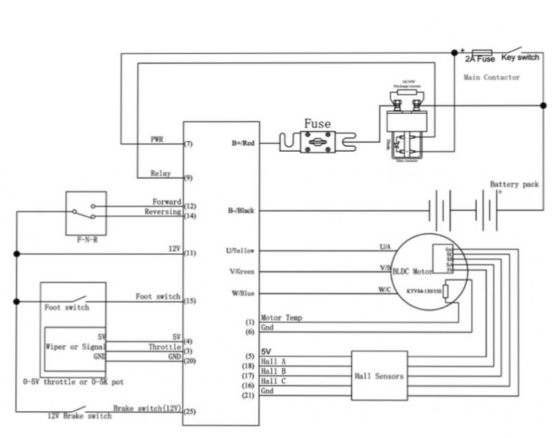
Looking at the wiring diagram from Kelly in the controller documentation (see below) they show the contactor being controlled directly from the 72v circuit protected with a 2A fuse. Looks a bit dicey to me - has anyone done anything similar here?

AF59-AD28-E52-D-4-F33-B05-A-1-C84-CA787-C9-C.jpg
 
This is what I did to my scooter with my Kelly controller and QS motor. No issues since I did this and use the scooter very often.

https://oi177.photobucket.com/albums/w202/mistercrash1964/Motorino/XPn%20wiring%20diagram_with_kelly_ca1_zpsc25qvreu.jpg~original
 
Thanks for the reply - the resolution of the image is a bit low so not that easy to see the wiring - you don’t have a higher res image do you?

I’ve also looked again and I’m going to wire the contactor into the 12v bike circuit as it won’t cope with 72v operating the solenoid. Also I want to provide 72v to the pre-charge resistor first on a separate circuit and then operate the contactor.

So given this can I ask if anyone knows if pin 7 on the Kelly controller needs 72v or can it cope with 12v? I now realise this is how the controller pre charges itself before the contactor supplies the main 72v feed.
 
Many thanks T.C. for the quick reply - I’ve been searching this forum and internet for days and clearly missed the post here you pointed me at!

I think I’ve got it all worked out now - I will use the 72v I’m feeding to the pre charge resistor across the contactor also to pin 7 on the controller with a 2A in-line fuse - this is switched on the main bike ignition.

I then have a kill switch that I’m using to switch the same 12v from the bike circuit to the solenoid on the contactor which opens the main 72v feed from the battery into the controller (the B+ post which is fused on the controller).

I can’t get out to the garage to try this now until later tomorrow but hopefully should work out ok now.

My only question/doubt is that on the Kelly wiring diagram it shows pin 9 as the ground for the solenoid on the contactor - I believe this is so that the opening of the contactor is controlled by the controller rather than in my case a separate kill switch. There’s a risk in my set up that if I arm the kill switch too soon after turning the bike ignition on then the controller and the pre charge resistor on the contactor won’t have done their job and I wreck both contactor and controller either straight off or eventually through arcing.

I believe if I give it a good couple of seconds I should be ok but again any views/comments on my approach here would be most welcome.

Thanks again for all the comments so far
 
Can confirm. I use a 72v contactor and switch on/off with 72v.

Also can confirm, pin 7 needs full pack voltage.

Be careful with the 12v (pin11) lead, it's meant just for switches. Don't pull more than 2a max.

The ground at pin 9 is common with pins; 6, 20, 21. Your solenoid should be diode isolated, just pre-charge as planned and you should be OK.
_______________________________________________________________________________________________________

Might I also recommend using a dc/dc converter in place of a separate 12v battery. It would help keep your weight down, plus you wouldn't need to maintain and recharge another battery.

Granted, it would reduce your range by a tiny bit since it's sharing the main battery. But if you calculate the total amount of amps you need for all your 12v goodies, there's bound to be one online with a matching output, minimizing the loss of range.

Personally, I tend to overbuild things, as in I use 2 dc/dc converters with isolated outputs on a 3 way switch, if one fails, I switch to the other. I ride a lot at night and can't afford not to be seen.
 
Thanks 2WheelsMovesTheSoul for the additional input - very helpful.

I wasn’t planning on using the 12v pin out from the controller itself (pin 11) as I do have a 72v to 12v convertor. Keeping the bike’s 12v battery was more of a failsafe but I agree it’s additional weight that I can probably do without, and would be better building in another 72v to 12v convertor as a back up.

On other builds I’ve seen the 12v circuit and relay used to operate the pre-charge resistor across the contactor and switch the 72v feed in, providing isolation of the main 72v battery. In my case my pack has a Bluetooth BMS built in which allows me to switch the charge and discharge ports on and off so I would be using this on the bike to overall switch the 72v pack on and off.

Can I ask do you use a single key switch on your set up? I’d planned on using the ignition key switch on the bike to activate the pre-charge resistor across the contactor, and then a second kill switch to operate the solenoid on the contactor.
 
I actually use a simple marine style battery switch for basic on / off. I have a large yellow/red pull in case of fire on the removable key. Shuts off all circuits on the bike.

Once I press and hold the pre-charge momentary button for 5 seconds, I put in the red plastic key, turn, this powers up the bike and dc/dc converters.

Once the dc/dc is on and running, my 12v motorcycle alarm must be disarmed. Once disarmed, a relay opens and allows 5v to the throttle.

I also use the 3 speed option, even though I have a 3 speed switch on the bars, the #3 or high speed won't work until I hold a button on the alarm remote to latch an optional output, closing a relay that interrupts the high speed input to the controller.

Keep in mind, I also use an even smaller dc/dc permanently wired directly to BMS that gives a 12v 1a output to power my GPS tracker and alarm. There is ALWAYS a load on my battery.
 
Thanks for all the feedback/comments so far on the thread here.

Having looked again, and taken some advice outside of the forum here, I believe my best option is to let the controller do the switching of the contactor, rather than do this with a separate circuit/switch.

I want to use the contactor I’ve got, where the solenoid/activator circuit is rated at 9-36v so latest plan is to follow the Kelly wiring diagram as-is and have the controller activate the contactor relay/solenoid using a 72v to 12v convertor to step down the activation voltage across pins 7/9. I’ll also ditch the pre-charge of the resistor across the contactor via a separate switch and relay, and wire this as per the Kelly diagram above.

I have ability to switch the charge and discharge ports on the BMS via Bluetooth so will be using this to control the battery output itself.

Will post an update once I wire this all up.
 
I see a bit of a discrepancy with the controller having relay control. I know Kelly was removing this feature on some other models of their controllers. And according to KLS-H manual V1.1 from June , 2019 it looks as if it has been removed.

https://kellycontroller.com/wp-content/uploads/kls-h/KellyKLS-HUserManualV1.10.pdf

Perhaps you have an earlier model. and if you have a terminal #9, and it works... no worries. :) Something I would verify first... :wink:
 
I got my controller in early May 2019 so am assuming it predates this version. That said in v1.10 of the controller documentation I’ve been using to date does say that all RTN pins are internally connected so I suspect they’ve just dropped pin 9 as the relay RTN. They still show the contactor being controller via the controller itself plus I see they added a low speed switch pin in this version which I definitely don’t have.
 
I was wrong - just checked the plugs and individual wiring and it looks like mine is the latest controller as I do indeed have a pin 22 blue wire!

Good job I hadn’t started wiring up the other end of the plug today :)

So it’s pin 6 I need to use as the GND for the contactor relay/solenoid.

Many thanks TC for pointing this out - I’d not checked back on the Kelly site since I got the controller and hadn’t seen this latest June 2019 revision of the documentation which is my bad.
 
All wired up and successfully got controller fired up and Android app connected via Bluetooth.

So far managed to complete the Angle Identification process with the QS motor which all went through fine without any errors.

Tomorrow will test throttle inputs - wheel is mounted on a test jig as not fitted to swing arm yet so am limited to sensible motor speeds for now.
 
Hi know this is an old thread but I wondered if I wanted to run a off road light bar off the 12v circuit but as I read earlyer up the thread it was only strong enough to run a small led light off..
Would it be easyer to to get a separate battry and forget wiring it though the kls controller or is there ways round it?
I don't care about putting a sag on my pack but I would like to utilise the space I have and prefer not to add extra battrys to the frame..
Further read that an average 6'' light draws 2.2a would the 12v circuit cover that?
Any helps much appreciated
 
Thanks mate that's great looks like it will work would you I'm pushing it to run a 18w light bar? or am I pushing it
 
Time to get out the calculator.

The Kelly 12 volt supply is 40mA. Which is .04 amps (point zero four) Mainly just used for electronic, very low current devices. IE: hall sensors and brake logic control...

A 18 watt light bar requires (watts = Volts X Amps) so 18 watts divided by 12 volts = 1.5 amps.

So according to my math, you are no where near the required current supply for your light bar coming from the controller's 12 volt source... :(
 
Back
Top