Whereswally606's Emax Scooter Thread

Joined
Jun 19, 2011
Messages
1,164
Location
Cheshire, UK
Great success this morning, managed to ride the E-max to work without incident 24.4 miles. Was a long old ride which I was not absolutely sure that I had battery capacity for (60ah 16s blue Calb cells did fine). The scooter has the old proud eagle controller and so will not put out the power required on hills to do 30mph and flat out down a hill with a good following wind you will be lucky to hit 40mph. :roll:

I was nonetheless impressed with the scooter. I forgot to wear thermals on my legs and so they currently feel like they are thawing out. I intend to upgrade the scooter to a 11kw Lebowski controller with 24 or 26s. That should give me the speed and acceleration to feel a bit safer in the national speed limit parts (60mph in places) of the commute. :shock:

Will post some pictures when I get the chance and make this thread my on going upgrades blog. :twisted:

Here are a few other ES members who have converted their Emax 110s or 90s who have threads dedicated.

UK, Brighton - Flexy
https://endless-sphere.com/forums/viewtopic.php?f=10&t=38617

Aussie - Jonescg's
https://endless-sphere.com/forums/viewtopic.php?f=10&t=71698

UK, Knutsford - BobC
https://endless-sphere.com/forums/viewtopic.php?f=10&t=81681
 
Have upgraded my scooter for more storage, I received a new rear rack from @vmoto-uk.com. Richard Jordan and Natasha Terinova have both been very helpful when it come to sourcing parts and giving technical advice on the E-max scooters.

I can report it fits and is a stronger design than the older style ones.

I have just received my replacement chip 2.70 version from lebowski and will be looking to build my controller using 3 mti85w100gc 3phase full bridge kits.

Many of my design ideas are in this thread but I will post future ideas here to help keep his thread from diverting off entirely.

https://endless-sphere.com/forums/viewtopic.php?f=30&t=55641&start=120

this is a link back to when I began adding my power stage musings to the Low Inductance output stage construction thread which is in my opinion a brilliant read.

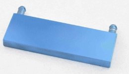
my current design idea is to use 3 mti85w100gc 3phase full bridge kits paralleled with themselves so that each chip is a single phase full bridge. Cooling has been calculated as needing a 0.5k/w heatsink which should be placed in the direct airflow on the scooter (i.e. cooling most when the scooter is working hardest). I haven't been able to find one which would be easy to place on the bike and think a better solution would be a water cooled solution using one Aluminum Water Cooling Block for CPU Graphics Radiator Heatsink 122mmx41mmx12mm:

watercooling block.jpg

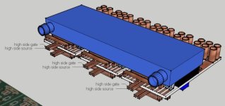
which will go in place of the heat sinks in this approximate design


the water pipes will be hidden by the fairings of the scooter and loop to a radiator placed in the airflow behind the front wheel. Hopefully this will be more secure and provide better cooling for when the controller is moving the motor at lower speeds up hills than just bare heatsinks.
 
Good choice, I picked the same size for 12x TO247.
Banggood has some nice pumps (100°C, brushless), e.g. http://www.banggood.com/DC-12V-Solar-Hot-Water-Circulation-Pump-Brushless-Motor-Water-Pump-p-972393.html, not sure about radiator yet.
 
Hi Andy
we watercooled one of the greenpower cars (before realising it was against the rules & got disqualified...) so I might be able to get hold of a little water pump & some pipe for you.......
On another note I can't help myself - I really want to have a play with one of these e-scooters... did you say you may know the location of one......??
I have a shed load of big old outrunners I'd probably try to use, so a fairly comprehensively buggered one would be ideal....
 
yes bob I know the location of 4, you may borrow or buy one off me at your convenience. I could do with the garage space back.
you may need a trailer to get it to yours.

They all run but they aren't all MOT'd,they are all large hub motor driven though.

I think you're after sometime like a Peugeot Speedflight. but ive no idea where to get one of them cheap.

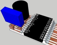
couldn't help myself with the design so I have done another iteration.

mti85s with the Lebowski board with watercooler.jpg
 
Glad to hear the scooter is thriving on lithium!

My scooter gets plenty of use now that I'm living in Albany - 31 km round trip, all of it at full speed (68 km/h). I average about 60 Wh/km in the cold.

Racked up 3850 km since October last year :D
 
old proud eagle maxes out at 35mph, 40 downhill with a prevailing wind ;) this is why it needs all 26s lifepo4 and a controller upgrade. Some of the roads are national limit 60mph single lane (bad to only be able to do 35mph). I do a 50mile round trip but charge at home and at the office. racking up the miles slowly but surely.
 
just had a quote back from mouser for the MTI145WX100GD which is another isoplus dil chip similar but not identical to the MTI85w100GC.

min quantity 28, £20.300 each, £568.40 total. Probably not going to use these.
VDSS = 100 V
ID25 = 190 A
RDSon typ. = 1.7 mW

which is a better spec when compared to mti85W100GC
VDSS = 100 V
ID25 = 120 A
RDSon typ. = 3.2 mW

but these are £13 each in batches of 10 or more. Shame really but the 85w looks like the winner on price :(
 
Andy
give me a few days, I'll try to get in touch with the ixys rep, use my work contacts :)
Of the 2, the 1.7mohm will give reduced losses so it will let you pull more amps, but if the others are cheaper and already do enough they'd be favourite.
 
actually £ for £ or pence for pence the 145w is better amps for your $ (marginally) although it does have almost half the RdsOn which I would like if I could get them without spending £500. my other concern is replace-ability And the foot print has all smaller legs which you are not as keen on which would change the design a bit. But please look into it as it has the potential for a more powerful power stage.

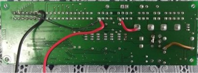
had a go at doing a preliminary sketchup for the 145w, will have to have a double layer to take the gate connections under the chip away from the chip. (i.e. to not cross the DC power path)

MTI145WX100GD PCB idea1.jpg
 
I've requested a quote for both :)
The package effectively limits you to 40W dissipation. If you assume that the dissipation is I^2R your amps would go up in the upper 30s percent - sure it's worth having, but you don't get the 190A vs 120A headline figure off the data sheet....
To take full advantage of the bigger dice in there, you'd need a bigger package. But it's the same package.......
 
Been reading lots of zombies threads on his driver boards using the TD350E driver chip. Really think it would be smart to get 3 off his boards created for my powerstage to help prevent killing the mti85w100gc chips. Also been getting quotes for sinewave controllers.

Sabvoton quoted me $305 delivered for either 72v 150a new or old model. £ 208.06 GBP

Powervelocity.com quoted $289 delivered so they are winning on price. £ 197.26 GBP

I think it will be a while before I have a working controller going the lebowski route but would like to be able to do 40 in a 40mph and at least 50 in the 60mph roads sooner rather than later. The other big challenge with this is maintaining all the ancillary bits working i.e. the speedo, lights, indicators. All done before in Flexy's E-max conversion thread so I wont be threading completely new ground here.

The other thing is I don't want to compromise where it comes to the lebowski controller financially. If I have a 72v controller on the bike already I wont feel pushed to rush it and get something wrong.
 
whereswally606 said:
Been reading lots of zombies threads on his driver boards using the TD350E driver chip. Really think it would be smart to get 3 off his boards created for my powerstage to help prevent killing the mti85w100gc chips. Also been getting quotes for sinewave controllers.

Sabvoton quoted me $305 delivered for either 72v 150a new or old model. £ 208.06 GBP

Powervelocity.com quoted $289 delivered so they are winning on price. £ 197.26 GBP

I think it will be a while before I have a working controller going the lebowski route but would like to be able to do 40 in a 40mph and at least 50 in the 60mph roads sooner rather than later. The other big challenge with this is maintaining all the ancillary bits working i.e. the speedo, lights, indicators. All done before in Flexy's E-max conversion thread so I wont be threading completely new ground here.

The other thing is I don't want to compromise where it comes to the lebowski controller financially. If I have a 72v controller on the bike already I wont feel pushed to rush it and get something wrong.

Go for that option. I'm kind of hamstrung by 96V so the outlay would be a good bit more (and have two motors in my silly setup) so I'll bite my way through.
Board has arrived fine BTW.
You'd have a proven design to fall back on as you rely on your scooter to go to work.
So far I have blown 2 Lyen 12FET 4110 & 2 MW power supplies. Reliability can't be overstated :)
 
looking at how to get this working on the bike now with the MCU. In flexy's thread
yokeamcity posts a very helpful couple of drawings but Flexy gets his working in a more reversible way.

flexy said:
I got stuck with the rest of the wiring;
I got the MSU to work from the 72-48v DC/DC ,when I turn the key, it turns everything on including the new controller.
When I turn the main lights on, it shuts down and restarts the MSU and "system error 01" appears on the dashboard.
According to the instructions this means
'Memory of speedometer defect. Exchange speedometer if message is still there.'
Very frustrating :(

followed by

flexy said:
I found a workaround.
I was taking a 15V output from a pad on the controller pcb to switch on the MSU, it turns out there is too much current draw when the scooter lights are on.
So now I have added a 48-12V DC/DC to power pin 8 on the MSU, this is turned on by a relay, which is switched by the 15V controller pad.
Now the lighting works and the bike turns on and off from the key switch :D
This has added more complexity and the 2 DC/DC's will be a battery drain.

yokneamcity said:
I connected it in this way.
+12V to CN1_pin8,CN3_pin1,CN5_pin1.
-12V to CN1_pin13/14.
I unsoldered Q3. This mosfet worked in PWM mode and supplying 12 volts to the light (from 48 volts).
I shorted R58/R59 resistors for the signal horn.(Now it work with 12V instead 48V)
I also unsolder the relay and short it. But do not necessarily.

View attachment 1
MCU_2web.jpg

So it appears there are two ways to skin this cat but I like flexy's method since I think for the sake of redundancy. if the controller dies for whatever reason and I need to get home I could have a toolkit on the bike and literally wire back up the old insitu controller and go back to 16s lifepo4 config. I suppose actually neither solution actually prevent this, hmm. the two DCDC methods is easier though.

Another thought I had after having a conversation with BobC the other day involved a amp meter and speedo which is based on a servo to give an analog needle to show the speed and amp at a press of the button. This was based on a arduino but I thought it would be a good way of getting a visual output of other parameter on the bike output on the old speedo face.

Fortuitously I have a speedo which is broke on one of the mopeds so will see a) if I can fix it and b) if not whether I can build a bobc Arduino device to show me a little more.

I also took the dimensions of the power velocity controller and did a mock up of where it might fit on the E-max. This may be the next post.
 
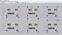
Okay more work on the Lebowski controller, I was told about the LTSpice theoretical circuit modelling software by Bobc, Today I downloaded it and has a play, it is fairly easy to get started and I just copied out the schematic for the MTI85w100GC which I intend to use, but as there are no values yet this could be any 3 phase full bridge.

mti85w100 LTspice.jpg

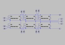
I also want to have a go at using the boards Zombies using on his 18fet controller with the desat limiting td350e chips and will have a go at modelling the whole circuit once I've figured out how this all works.

mti85w100 LTspice2.jpg

A bit more playing, tried to find an n-channel mosfet which matched the closed with the values on the datasheet and added the net labels, haven't had much luck matching the source-drain diode from the datasheet spec.
 
Another Idea for future improvement, This one I would definitely need MSVA for, no chance of not being detected.

So I was reading a post from spinning magnets and saw bikeweb which is all about feet forward motorcycles. I think I had this idea independently but seems nothing is original and this idea has been around for about as long as motorcycles have been being produced and subsequently modified by their owners.

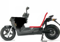
I've been trying to get the scooter to go quicker and one proven way to do this is reduce the forces acting against the movement i.e. in this case air resistance. The E-max would be well suited to this as its really just a low down battery with two wheels. The feet forward lower seating also lowers the centre of gravity further (which is already low thanks to the battery location), which should help to corner.

Anyway I did a little mockup in paint to see how it might look. Needs a Vetter fairing but I think it could work.

E-Max-Scooter crude feet forward.jpg

obviously its not this simple, but its not that complicated either. Contacted Royce Creasey of feet forward Voyager fame and he has achieved 0.21Cda on his Monoliner race development project. Something to aim for there, better than my Honda insight :shock:
 
Link is broke can you post the whole link in clear text?

Sent from my ALE-L02 using Tapatalk
 
Thanks parallbellum

Sent from my ALE-L02 using Tapatalk
 
New E-max 110s owner Bobc,

After a successful snipe at £80 last night Bob has become the proud owner of a lovely red 110s.

We had a good roast chicken lunch and discussed some potentials of the lebowski controller and streamlining and even had a test ride on my E-max albeit a very short one.

Bob brought over some wine and a usb key containing as LTSpice model of a theoretical powerstage for space vector modulated sinewave input and an excel sheet which help work out the losses when running a 3 phase bridge using the values of the mosfets and the frequency of switching. The good news here was that the mti145wx100gd may have enough juice 8kw in one chip alone making the power stage very small. It is at least a [strike]good[/strike] great place to start.

If anyone local to Manchester would like to join us in this journey of conversion of the E-max 110s 2008 then I have one spare which I will sell for £350 in silver). As you can see you can buy they for £80 but this one is a runner and I've never seen anyone get one as cheap as bob did.
 
Looking forward to working on this. It was fantastic to get it for a good price, mainly because it reduces my worries about gutting the thing to put my own drive system in. The item is advertised as having a charger fault so it's likely the batteries are "doorstops" too, but if I'm lucky I'll be able to make it go in standard form before taking out the hacksaw....
When things get interesting (for us weirdos) I'll start a thread. As andy said, he's given me a controller board, I'm buying a couple of chips from lebowski; I've got lithium battery management ready from other projects; I will be interested to see if I can "soop it up" to reach 50, if I can do that simply and cheaply it becomes a very capable commuting tool for me! Thanks for dinner Andy - it was so much better than I would have made for myself & it was lovely to see pip again & meet Isla!
Initial impressions are that a single ixys 6 pack should get us up to more than 7kW on 20s Li battery, but that depends on me keeping transients and overshoots under control in the inverter - it will be an interesting journey!
I expect I'll be collecting it on Wednesday - gives me a couple of days to find some room in my workshop.... (which is VERY full already....)
 
i would recommend that you guys use the temperature sensor input of the controller IC to protect the power stage. It will then automatically reduce the max phase current when the powerstage gets too hot...
 
Picked the bike up last night. And now - quandary - the thing is just so nice - it seems a terrible shame to gut it...
Lebowski, the ixys 6pack doesn't have an NTC (or other temp sensor) built in so it would be fitted nearby on the heatsink - yes some kind of overtemperature protection is a very good idea during operation, though you at some stage have to test the thing without or it messes up measurements... I dimly recollect that your software has an adjustable temperature curve so you can adapt to 'any' temp sensor(?) and read true temperature.
 
I was thinking about putting the temp sensor on the heatsink along side on the surface which the ixys chip is touching, should be close enough I think. Then about 4 in different places in the hub motor and a few in the battery pack.

Been looking at hub centred steering. looks like there has been improvements over the year and the new (maybe vapourware) lit car uses it. This is way off though.

Keep me posted about when you have the parts ordered Bob, getting keen to start work on mine. Great to hear its in good condition. looked great on the ebay pics.
 
Back
Top