BobCs emax scooter thread

bobc

10 kW
Joined
Jan 20, 2011
Messages
993
Location
Knutsford England
Bought Sunday night for £80
Transported home Monday night £20 (petrol money to my mate Richard)
Tuesday night:
1) try it out - went 12 yards before cutting out "low battery"
2) start dismantling... First "faulty charger" would appear to actually be "melted charging fuse holder". OK it might also really be faulty charger, but changing the in-line fuse/fuse holder may very well fix that problem :D .
3) pull more panels off - damn the floor is "push forwards" to release not yank it off like an idiot & break all the tabs: I'll start glueing.......
4) monster batteries revealed. All have lots of OC volts, started giving them all a slow charge (<1A) & will discharge test them individually in a few days

Looked on-line for lithium replacement costs: replacing with lead looks like say £500
replacing with LifePO, just 60Ah and 23s looks like around £1800 - very "ouch"
replacing with 18650s say 20s 20p looks like around £1500 (ouch) and a load of work....

I see now why Andy (whereswally) is doing what he's doing - with the "calb" cells the lead acids can be swapped out directly and more volts brought in later when an uprated power module is on line - that's quite tempting if my SLAs are toast...
 
yeah, sorry bob should have at least demoed how to not take it apart. I have a maintenance manual printed out if you want to borrow that too. I was very very lucky with the blue calb buy since they were not new but were pretty unused and thus unabused. The newer grey calb are much better spec though. There is a chap at indra who is selling sinopoly lifepo4 of ebay who might do you a set but i've no idea of the quality
One option which is very low work and high spec for least outlay is the leaf modules out the Nissans. I think if I hadn't snagged a bargain on the calbs I would have gone done the leaf modules or the 18650 route. I think you won big time on the price of the E-max, money saved that should go giving the thing a decent battery.
 
how funny a green man sticker. I suppose that's kinda appropriate.
 
That's what that is...... :)
Batteries being charged at ~0.7A, seem to be taking a charge alright (they're now all up near 13.8V)
I have a discharge tester that I made for the greenpower racers so I can use that to see what the batteries are still good for. (it's a 0.75ohm resistor that disconnects itself at 11V, with a timer to show how long it took)
The charging lead on the bike has an in-line fuse which the holder has all melted & is now open circuit. I'm hopeful that replacing the fuse holder will make the original charger work again - fingers crossed!
But I'll give it a couple of long slow charges first to gently wake up the batteries from their long slumber.

I've started looking at the inverter; it's a self contained module which I should be able to swap out lock stock and barrel for a home made one with more battery volts. The Lebowski "brain" and the ixys module "brawn" would appear to be a perfect match.

So - power module switching; first choice, how fast to switch? Faster switching (dV/dt and dI/dt) reduces switching losses but increases EMI and starts giving rise to EMC problems. On mains inverters I try to keep dV/dt down to 5V/ns (most signal isolation solutions still work at this speed). dV/dt is controlled by the gate driver current into the miller capacitance (Crss). These FETs have Crss = 70pF and that, multiplied by 5V/ns means I need 0.35A of gate drive. If I assume gate drive power supply is 12V and the MOSFET Vg threshold is 3V, that's 9V of overdrive so I need a gate resistance of 9/0.35 = 25ohm. I'll put 27ohm in to start with.
Note this is the 'on' resistance; switching off we only have Vgth (if we pull down to 0V) i.e. 3V of drive, so the off resistance should be less than 1/3 of the 'on' resistance.
Always worth a check that the same miller effect doesn't switch on the "off" FET when its opposite number switches on (i.e. at the end of the dead time). In this case we have a capacitive potential divider with 80V delta V through Crss (70pF) to the gate with the gate's own intrinsic capacitance (Ciss = 11.1nF) to source. That potential divider intrinsically gives just 0.504V step on the gate, so the unit shouldn't immediately "shoot through" and detonate.
How do we control dI/dt? We have some control by placing extra capacitance between gate and source. The transconductance of the FET is around 500A/V in the 'active' zone, so to get 4A/ns drain current dI/dt we need 8V/us on the gate. We know we have 0.35A in the gate drive so that means a total of 44nF gate to source. It already has 11nF in the silicon, so I'll probably fit another 33nF next to the gate; we'll see what it looks like if I get that far.
If I put those figures into a simulation spreadsheet at 100Arms and 10kHz switching frequency, I get inverter dissipation = 69W. That's efficiency around 99% (not bad).
That is essentially the gate drive design done, I'll probably also pop some 15V zeners gate to source to 'belt and braces' protect the FET gate oxides.
Next thing I'll look at is DC link design; battery and capacitor banks. I've not yet decided what to do about inrush..
That turned out to be a bit of a novelette: The DC bus discussion will have pictures from LTspice, it quite nicely demonstrates why you need electrolytics AND film caps near the switches...
cheers
Bob
 
First battery discharge test well under way, it has been supplying 17A for nearly 3hrs, so it still has half its capacity with more to come. Hope they're all this good!

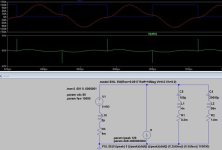
OK I've been looking at the DC capacitor requirement for the inverter. The physical size of the batteries puts them in a big loop. Just using an on-line calculator and assuming a loop 200mm x 1000mm gives me a loop inductance of 2.5uH so I've simulated with 2uH. I estimated the battery series resistance to be 0.004ohm

The load on the DC link is a chopped waveform with a peak value equal to the output current peak. So I simulated this as a square wave of current with a 120A peak with the frequency of the square wave equal to 2 x the switching frequency of the inverter. Here one should not switch the load current instantly on & off, it should have a risetime determined by the gate drive circuit calculations in the previous post. The simulation has parameters for Ipeak, dI/dt and fsw

Here is the simulation
DClink.JPG

Capacitor banks must be added now to try to keep the DC bus within safe limits (0 to 100V). Higher transients will be soaked up by avalanching in the MOSFETs - avoid if possible - this shouldn't be fatal but it does reduce efficiency.

Aluminium electrolytics are good to control switching frequency ripple. I've made a guess at 11 1800uF EPCOS caps from RS (their #771 4743) This bank would have ripple current rating of 50Arms, which is close to the red simulation trace. Note that I don't expect the drive to run with a current or voltage level that would generate so much ripple for extended periods - this would be mid speed and high torque - say going up a long hill. You can see that there is sufficient capacitance to keep the switching frequency ripple (on the green trace) to around a volt pk-pk.
The parasitics associated with the 20000uF are 1.8mohm (from datasheet) and 96nH (based mostly on geometry, estimated a rectangular loop 100mm x 10mm)

This large loop inductance means that the AlCaps can't control things during switching so an extra nearby capacitance is needed (near the half bridge FETs). Here I went for a polyprop film capacitor RS# 888 0911 (one for each 1/2 bridge) which is probably way over the top, but I figure I should spend up front to avoid problems rather than spend later to fix 'em.... These are 47uF each with very low ESR. Again the series L is probably going to mostly be in the geometry. 4nH in total (that would be 12nH each of the 3 parallel) is good enough to keep the DC bus in spec with a switching rate of 4A/ns.

The simulation picture is LTspice, it's a free download. The above shows that it is a relatively simple task to make a useful and informative simulation of what might otherwise look like a black art - I'd urge anyone to have a play.

That's how the DC bus on the inverter will be designed on the prototype. It's considerably more amps and fewer volts than I'm used to; hopefully the simulation (and others like it) will help me to avoid some of the bear traps this field leaves around!!
Bob
 
regarding the di/dt, you've based this on the slopen of the gate and the FETs transconductance.

I always assume the di/dt to be based on (near instant) voltage step equal to battery voltage, combined with the inductance loop going through the half bridge, power busbar and bus caps. Assuming 80V and 20nH, you get 4A/ns and no need to add extra caps to FETs...

For the dV/dt during switching, I try to aim for equal switching losses at max phase current for conduction losses and switching losses. Then

Ttot = Ton + Toff = 3.14*I_amplitude*R_on / (2 * Vbat * f_pwm)

with Ton and Toff the time where the output rises linear w.r.t. time as you have calculated. I typically make Ton twice or three times Toff, this then automatically keeps the off-transistor off when the other switches on and controls the slope.

Last, I find the Cgd number form the datasheet unreliable, it is actually a whole curve. Better is to just to measure Ton and Toff (the length of the Miller plateaus for the slope controlling FET) and reverse calculate the Cgd.
 
Thanks Bas - I wondered if anyone was looking..... I'm sure you're right, you don't see many folk loading up their gates with extra capacitance. I'm just applying the same rationale I use at work on industrial (mains) inverters. On which, you can argue about the downsides of slightly reduced efficiency but there's nothing like actually being in control of things rather than just letting nature take its course... My german colleagues traditionally switch their IGBTs absolutely as fast as they can, and have then spent a lot more time and money achieving an EMC solution which passes legislation, solving EMC issues due to common mode dV/dt exceeding isolator max specs etc etc etc.
When I build one I'll have to remember to do a leg without extra gate cap & see if it's any different :)
I'll also be very interested to see if a capacitor solution on the simulator does the business in reality - I've got a general plan for layout, we'll see how it translates onto FR4...
 
Battery tests; I made a discharge tester for the school's greenpower racers. It's a fan-cooled resistor that switches itself off when the battery volts drop to 11, with a timer to tell you how long it took. It discharges at 16A.
3 of the batteries took between 2hrs 30 and 2hrs 50
The other took 3 minutes. I think that one's dead. Luckily whereswally is just a few miles away & he has just swapped his lead acid for lifepo4, so he said he'd lend me one to get the scooter going (thanks Andy!)
Also I thought the accumulators were 100Ah - no no no, they're 68Ah (at 0.2C). (size 170x260mm and 210mm high) So I could use 40Ah lithiums for my purposes - easy enough, that will save a pile of money. Andy says the smaller emax have exactly the same battery (I thought they had a space filler liner in the battery compartment and smaller batteries) 24s Lifepo4 at 40Ah would be around £1000
 
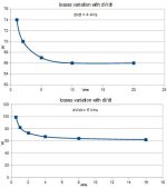
And here's another simulation; this ones a spreadsheet which uses device characteristics to determine inverter dissipation. I wrote this myself for work (so I can't really share), had to do it because nothing available modelled diode reverse recovery properly. In a FET inverter reverse conduction is generally taken care of by the FETs (They're unipolar & conduct as happily backwards as forwards). But during dead time, current switches to the built in body diodes so you still get the reverse recovery losses due to that, just not the conduction losses. Anyway I did a series of runs varying the switching speed (dI/dt and dV/dt) to show the effect and importance.
switchingloss.JPG
First note the vertical scale; losses are more strongly affected by dI/dt. Industrial drives operating at much higher DC bus voltage, it's the other way round and dV/dt has greater effect.
1) dV/dt
Looking at these you'd say the dissipation has effectively bottomed out at 10V/ns. It's just 1W worse at 5V/ns - seems reasonable to me.
2) dI/dt
We've increased dissipation quite a lot at 4A/ns (c.f minimum). I'm still going to try to run there because I don't like induced voltage spikes of 80 to 100V in the vicinity of a MOS gate (gate oxide damage can be a cumulative failure mode...)

And I did a quick solid model of the battery compartment & some lifepo4 cells - no problem at all fitting in 24s of 40Ah. I'll have to see how many series cells I can do....
 
I've been looking for batteries; spoke to "indra" near Bristol, they fence sinopoly lifepo4 prismatics and 40Ah at 24s should set me back around a grand. Any feedback (good or bad) about these parts/supplier? There seem to be quite a few "prismatic" suppliers (calb, Winston, sinopoly - they all seem to be very very similar in price/size/specifications. Thanks for the link andy, those prices look quite keen but I fear I'd be hammered by delivery and import duty. I get the impression that the prismatics need to be "clamped" or they can balloon alarmingly with the slightest mistreatment & the geometry change ruins them if they survive the mistreatment... That's no bother, clamps are EASY :)
 
eeek do you think my arrangement is clamping the cells. They don't move at all and there is a bit of flex in the battery box for swell. I wander whether there are any uk places to buy from instead like breakers yards. You really only need find one second hand crashed leaf and you'd be set, or any recent hybrid.

Another option which is kinda great from the point of maximum control is 18650 cells, buy a shit load from tumich on here or straight from the factories in china. I have a spot welder board from riba on here to put them all together. You even have the skills to approach a battery recycler here like doctor bass does and get the konion ones from dewalt and other powertool batteries. Or lastly a A123 pouch build would maybe not be so difficult? they are 20ah pouches so you only need 48 of them, they are about the best lifepo4 you can get.

sendler2112 said:
I just ordered 26 of the welded tab AMP20 cells. $180 Shipping could be cheaper. With the 4% paypal fee the total came to $782. $30 each shipped. Not quite the bargain the $22 price made it seem. I asked about pricing on 50 cells but the shipping went up to $300 so it was not much savings. I didn't order any extra so I hope OSN Power has sorted them well to eliminate any duds. They say the capacity is similar to a new cell. We shall see.

from https://endless-sphere.com/forums/viewtopic.php?f=9&t=46395&start=225 only from last year so this may be worth looking at.

1054.77 British Pound for 50 a123 cells after $300 shipping. I would at least approach OSN and get a latest price.
 
Yes I think your arrangement IS clamping the cells - they're pretty much wedged in there :)
Unless I hear bad things, I reckon I'll go the sinopoly route - I like the idea of being able to check the state of every cell before I take possession :)
Thanks for all the information Andy, I do appreciate it.
Batteries - still charging away. I tried the 2 batteries from Andy's old scooter on the discharger for 10 minutes. They both sank to 11.7V after a couple of minutes then stayed there; it does seem to be taking a while for the charging current to start tapering down. The full batteries discharged at 12.2V FWIW
 
Put the scooter back together on Sunday and it all seems to work just like it's supposed to.
Booked MOT test for Thursday evening. I'll insure it that day too so it will be on the road!
I bought an ebay "boost converter" for about £13 so I should be able to charge the batteries from the 600W solar array on my south wall. I can use the same boost converter when I change over to lithiums later and choose to either charge from the solar SLA rack or from a small 48V PSU (£16 on ebay...). I do like the idea of charging from the solar array - it's the green dream.... With SLA batteries (scooter at present) I can just set the boost output voltage to 52V or so. When I change to LiFePO4 I'll control it (the boost converter) via the battery monitoring system detailed in another thread. I can still use the voltage setpoint as a backstop for safety (against crazy overcharge), but general operation will be to bulk charge the stack until the cell monitor detects any one cell over 3.4V whereupon the bulk charge will be switched off.
 
Amazing, just used. Mine today, went to work 25miles come home via pub for Thursday night pub quiz. Will be good to know you range on the lead acids

Sent from my ALE-L02 using Tapatalk
 
range check - - - not good - just 4 miles range, another battery looks bad (going up to 16V when charging). I'll put in the 2nd spare I got from Andy....
The bike feels a bit rough on the road - I think it needs some fluid in the front dampers and something tightening in the steering.
And I am really bad at riding a motorbike... hopefully that will improve...
The supplied (mains) charger works perfect
 
welcome to use my battery swap shop, got a few more on charge now getting ready for paralleling them all into a 12v bank. Will be great once you have upgraded to the lifepo4, trust me its a different bike when its that much lighter.

Riding will improve Bob, no excuses at the moment, weather is awesome.

Anyway the real fun will start when the lebowski board and powerstage are complete.
 
Thanks Andy - swapped a battery and tried again, 13 miles this time. I'll give it a few cycles see if it gets any better...
Or I might be going over to lithium a little bit sooner than I planned....
How many series LifePO4 do you run on the OE proud eagle? - 16s would be a nominal 50odd volts, but maybe the controller can take a bit more than that....??
edit - controller data says 63V max - that would be 18s (?)
 
I run 16s but you know it's cause they fit so well but you got me thinking I might up it as a test of the bottom balancer when that's done.

Sent from my ALE-L02 using Tapatalk
 
I'm giving up with the lead acids - I'm picking up £1000 worth of LifePO4 on Saturday then a day or two mounting, wiring etc. The 48V psu arrived last week and the (more important) boost converter may be here already at local post office. So I might be properly mobile using energy from my PV solar array next week!
Related projects: arduino/relay charger controller/balancer: PCBs still being made, other components and software all ready.
POwer stack upgrade - still waiting for news from IXYS - "converter brain" lebowski board, psu built, gate drives and current sensors mounted, waiting for some capacitors (there are 100nF caps on there with 0.1", 0.2" and 0.3" lead pitch - not complaining Bas... :)
It's all keeping me out of trouble....

PS the 13 miles in the earlier post was a subtraction error - real range is about 4 miles :(

PPS yes boost converter is here, and so are the balancer PCBs. I'll try to get the 12V SMPS going on 2 of them at work tomorrow :)
 
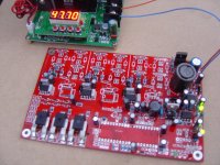
Buildup continues on the Lebowski board. Here's the onboard switcher in un-trimmed form (around 4.9V and 14.8V)
It's running off 50V there (that's my boost converter at the back)
lebpsu.JPG
 
Absolutely - that big inductor doesn't fit properly either, it will need a big cushion of hot melt glue to sit on.....
For reasons of component availability, I've had to be 'creative' with some of the component choices (not many visible in the bad photo above), that inductor is an example of this :) It's probably ludicrously oversized as I didn't know the current rating required (that's a 1.9A part!!!!!)
 
Back
Top