Reverse stutter from motor controller

jordan314

1 mW
Joined
Apr 3, 2016
Messages
13
I've hooked up an arduino to two chinese motor controllers. I'm using two digital potentiometers to mimic the throttle signals, and two standard 5V GPIO pins to the reverse switch lines to toggle reverse. It works totally fine going forward - when I increment through from 1.2V to 5V going forward, the motors go from stop to full speed smoothly. When I turn on the reverse lines though, only one motor operates and it stutters as it spins backwards. It also seems uneven - as it increments, 1.4V might go fast, 1.5V might be stopped, 1.6V might be slow, 1.7V might be faster...it's weird. I would think it was a problem with the hall or phase lines but it only happens going in reverse. Anyone have any idea why?
Also I'm wondering if my reverse line needs a pull down resistor or something? I have the GPIO going into the reverse input line and am not using the other reverse line that provides power. I figure the controller must already have a pull down resistor built in, or when the reverse lines are disconnected it would float and randomly go in forward and reverse?
 
Sounds like your hall sensors might have advanced or retarded timing rather than neutral. If so you might have to account for that in the signals being sent from your controller.
 
Hmm. Also when I plug in the learn line, unplug it, and plug it back in, the wheels run fine in both reverse and forward. It's weird.
 
If it works normally using the regular controller inputs from a throttle/etc, but not with the arduino, then you should compare the two with an oscilloscope to see if there is noise on the signals causing the problem.
 
I wasn't using a common ground, whoops! I hooked up a connection between the negative terminal of my two batteries, and one wheel responds smoothly in forward and reverse now. The other one doesn't respond, but works great in forward and reverse if I hook up a normal throttle. It must be something with my circuit, hmm.
Thanks!
 
Thanks amberwolf, guess I should buy an oscilloscope, comparing the signals is a good idea.
 
If you have a soundcard in your computer with a line-in, there are programs to use that as a scope (google around; there's a few; never used any of them myself).
Here's the top hit on google, as an example
https://www.zeitnitz.eu/scope_en

It's safest and more accurate (better impedance) to build a little isolating op-amp circuit but if the signals are low-level, and within the input range of the soundcard, you could use an old headphone cord to connect the signal you're interested in, directly to the line-in input (via a voltage divider to scale the signal to the soundcard hardware limit). Since it's a stereo input, you can actually check two signals at the same time, as long as they have a common ground, and the software supports that.

You can even just use any audio recording program that displays a waveform and allows you to magnify it in time and amplitude for display, if you don't need anything more than just to see what the waveform looks like. (I have done that once or twice years back, for simple digital signals that weren't really purely digital, which ended up being the problem...but I couldn't clearly see exactly what the problem was, and I just ended up SWAGing by swapping out the related parts on the problem board and it worked. A scope would've been way better).


But if you do a lot of this kind of work, a scope is real handy for checking stuff like this. Even if it's an ancient one like the giant old-as-I-am Tek 565a I had before the fire, or the little Hitachi portable I have now.
 
That's really cool. I've been considering USB oscilloscopes or smartphone ones such as the Mooshimeter, but don't know if they're any good.
https://www.amazon.com/Mooshim-DMM-BLE-2x01A-Mooshimeter-Wireless-Multimeter/dp/B011W4L7JA
Edit: That's a multimeter, something like https://www.oscium.com/oscilloscopes/imso-104
Thanks!
 
I've never used anything other than "real" scopes ;) except for that soundcard check I described above, so I can't speak to any of the USB stuff. There've been some discussions on ES about them, though, if you look up USB and *scope together.

You can find hardware scopes used, dunno how cheap they are these days. I've been lucky enough to get mine from friends that didn't use them anymore (and so they aren't exactly in perfect condition ;) ) but I've seen them in "salvage stores", ebay, craigslist, closing-company auctions, etc.
 
Hey Amberwolf,
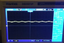
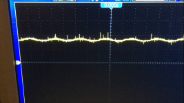
So I did buy a cheap oscilloscope (hantek 5000 series) and measured the throttle and the digipot. Both are outputting 1V-5V. This at least confirms that the hall sensor is analog and not outputting PWM. The blue one is the throttle and the yellow one is the digipot. Sometimes when the motor is running there is more noise on the digipot (photo 3). But nothing major I don't think. I think the sine waveform noise on both the throttle and digipot might just be my oscilloscope picking up my AC power, I'm not sure if my outlets are truly grounded but a lot of them aren't. I ordered a tester to check. Any thoughts? I see noise but it doesn't look too bad to me. I guess I can try the other wheel's line as well as the reverse lines to see what those look like.
FullSizeRender.jpg
IMG_0203.PNG
View attachment 1
 
If the problem is only happening in reverse then perhaps there is noise on the reverse line causing an issue.

What happens if you swap the controllers, so that the "working" outputs from the MCU setup are hooked up to the "malfunctioning" input, and vice-versa? Does the problem move, or stay the same? If it stays the same, then you have an issue with one of the controllers or motors. If it moves, then it's a signal problem from the MCU.

If the sine ripple is the same frequency as your AC power, then that's probably all it is.

Also, usually you wouldn't see it except at pretty high magnification--what voltage are you seeing for the p-p ripple?

If the ripple is very low voltage, then so are those little noise spikes, and are unlikely to be causing any issues. But if the spikes are high enough, they might cause undesirable behavior, if the spikes coincide with the behaviors. I don't see them on the throttle waveform, just the digipot--so if the behaviors only happen on the digipot, perhaps some capacitance, or an RC filter to eliminate them would also fix the behaviors.


Is the device itself AC-powered? If so, perhaps if the ripple is high enough and actually present on the signal or other lines, it could be disrupting normal operation.

If it is battery powered then it is unlikely the ripple has anything to do with your problem.


Another note--the hall throttle just outputs a voltage. The digipot simply has a resistance. Are you using the digipot with the wiper pin as the throttle signal, and one end at 5v, and the other at ground? If so, then it should simulate about what the hall does (usually something like 0.7v-0.4xV). If you want it to be closer, you can add a resistance between ground and the digipot's "bottom" pin, and another between 5v and the "top" pin, calculated so that the actual voltage output of the digipot is identical to what the throttle puts out. It's not necessary, but if you want the identical behavior, and a finer gradation of control with the digipot, this would do that.
 
Thanks! Yeah that's exactly right, I have throttle ground going to P0B, throttle high going to P0A, and throttle signal going to POW to get varying voltages. Adding resistance to match the signal on each is a good idea, thanks.
I think I may have gotten it working, I read here that I might need a 4.7K resistor between Hiref and Loref to prevent a fault on the controller:
http://electronics.stackexchange.com/questions/191854/how-to-emulate-potentiometer-to-control-electric-vehicle
I don't have a curtis controller, but trying that, now one wheel responds forward and reverse. I haven't tried both wheels yet though.
The device isn't AC powered. And it turns out my power is grounded, I tested it today. So I'm not sure what the ripples are, but I think I'm on the right track now.
Thanks!
 
Back
Top