Kelly controller key switch voltage

jhartzhe

10 µW
Joined
Oct 10, 2018
Messages
5
Hi folks,

First post so I apologize if I've done anything wrong. I'm sure this has been addressed in another post here somewhere, but I couldn't find an answer that I could understand since I'm not all that sharp.

I'm trying to replace a controller in a Green Bee electric scooter (https://websdecode.com/greenBee/metro1). I couldn't find an exact replacement, so I've gone with Kelly's KEB72450X. I'm not trying to do anything too fancy with it, I just need it to work well enough to get me 4 miles to work and back.

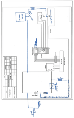
I've tried to wire the controller and contactor according to Kelly's diagram (attached).

I used a 24 volt battery first. At 24 volts, the new controller power on (green light illuminated) and them motor shuddered but did not turn when the throttle was turned. At 60 volts, which is the original voltage of the scooter, I got a pretty impressive cloud of smoke from the ignition key switch when I turned the key on.

I assume this means the switch was not meant to handle 60 volts (probably obvious but I'm pretty ignorant about electric vehicles). However, in the original wiring, it looks like the key switch got 60 volts from the battery, although its very possible I missed something.

Here's the question (sorry if the intro was excessive) - I I use the 60V DC to 12V DC converter to run 12 volts through the ignition key switch and coils of the contactor, what kind of switch do I use to switch the 60V supply to the converter on and off? Have other folks come up with a good way to do this? Or do I just need an ignition key switch that can handle 60V?

Thanks! I appreciate the help, I'm probably in over my head with this project.
 
It sounds like the main power for the controller was passing through the key switch and it couldn't handle the current.

In the Kelly diagram, they show a contactor (big relay) for the main battery wire. Does the scooter have a contactor?

If you are replacing a Kelly, the old one should be wired the same. The main fat battery wires should go straight to the controller if there is no contactor.

For any switch, it's not just the voltage that counts, but the current too and whether it is AC or DC. Most small switches at that voltage can only handle about 1A. Your dc-dc converter might be too much load depending on how big it is.

If you need to switch the main battery line, I would recommend a solar circuit breaker as these are built to handle that kind of load.
 
Thanks for your help!

The scooter did not originally have a contactor, I added one.

The original controller had no markings on it at all. I don't think it was a Kelly, and Fany at Kelly didn't think it was one of theirs, but the original description of the scooter from the link I posted claims they used a Kelly controller. I couldn't find an exact match for the original, so I ordered the Kelly one.

How would I prevent the main power from the battery passing through the key switch? I've got the large battery wire (+) connected to the one of main (large) terminal on the contactor, and the other large terminal connected to the B(+) terminal on the controller. The small terminals on the contactor are connected to the key switch and back to the negative terminal on the battery.

It sounds like you're suggest omitting the key switch entirely and connecting the controller directly to the battery, potentially with a circuit breaker in between, is an easier solution. What's the disadvantage to doing it this way?

Thanks!
 
The contactor is generally used on golf carts or cars but rarely on a scooter. Most people here don't use one. It is an important safety feature if you are using a brushed motor, but not really needed for a brushless motor. Just run the two main + and - battery wires directly to the controller. A circuit breaker or fuse should be used. I like the solar circuit breakers as they allow you to turn things completely off for service or storage.

The key switch should only feed pin 1 on the kelly. This take about 100mA or so. Any key switch should be able to handle this much.

The sticky part is the dc-dc converter. Ideally you want this to get turned off with the key but the key switch may not be able to handle the load. Any idea how this was wired originally? One option would be to use a contactor or smaller relay to turn off the dc-dc and operate the relay coil from the key.

Another option would be to power the big contactor coil from the key and run everything else off the contactor. Be sure the contactor coil voltage is rated for the pack voltage.
 
Thanks again for your reply, it's a huge help for me.

I'll try it again without the contactor, with the controller wired directly to the battery and pin 1 on the controller switched on with the key switch. Any recommendations for a circuit breaker for this set up? The battery pack is 60V, and the motor is 3000W. I believe I've seen a few threads on here about breakers, so I'll see if I can find something that matches my set up, too.

It looks like the dc-dc controller input was switched on by the ignition switch. There's a 2 amp fuse going into the converter on the 60V side. If I read the original set up correctly (which is a somewhat big if), the key switch on 60V to the controller power (not the main + , but similar to pin 1 on the kelly) and the dc-dc converter.

If its safe to leave out the contactor I'll just plan to leave it out, I don't really understand how to use it and I've had enough fun cooking switches for now.

Thanks again for your help, maybe one day I'll get more into understanding these vehicles but for now I'm just a student trying to get to campus for cheap.
 
It wouldn't be uncommon for the key switch to operate the dc-dc converter and the pin 1 line. If that's how it was originally, it should still work.

Here's a link to an example of a circuit breaker. This one is 100A, which should be about right for your application. You could possibly use a lower amp one, but you don't want it to trip unless something shorts out.

https://www.ebay.com/itm/MIDNITE-SO...90I:sc:USPSFirstClass!94903!US!-1:rk:17:pf:0
 
Thanks again for your help, just wanted to post an update in case its helpful to anyone.

I replaced the contactor with the Midnite Solar 100A breaker (MNEDC100). Not sure if the pre-charger resistor is supposed to be used for the breaker the same as the contactor, but I did not use it. So far, it's worked just fine. The key switch operates the dc-dc converter and pin 1 (PWR) on the controller, and that's worked just fine as well. I've tried to outline how I connected everything in the attachment.

Wiring.png

So just to recap for anyone that has a similar problem, I was having problems figuring out how to wire the contactor for a Kelly KEB controller as described in the Kelly manual wiring diagram. I replaced the contactor with a 100A circuit breaker and that's worked fine.

One additional question, if anyone has any advice. In the diagram above, I also drew the charger connection. Originally, the charger wires were spliced into the larger (+) and (-) wires between the battery and controller. I've connected the (+) and (-) wires to the charger port directly to the battery terminals, and added a 10A fuse. This makes sense to me, but if anyone sees any issues or has any suggestions on a better way to do it, I'd appreciate it.

Thanks!
 
Your charger connection is good. Better that way. If you ever upgrade the batteries to lithium, you want a separate charge port anyway.

A precharge resistor across the circuit breaker will make the contacts last longer, but perhaps unnecessary. If the breaker was turned off, but the key was on, the resistor would get hot and not precharge the controller. If you used a big 4.7K ohm, 2W or more, the resistor shouldn't burn up if you get the sequence wrong.

The advantage of no precharge resistor is when the breaker is off, it's really off and there won't be any power going to the load.

Others have used the solar breakers without a precharge resistor and had good results.
 
Back
Top