Yamasaki YM50-RE Build

swiftyds

100 W
Joined
Oct 24, 2017
Messages
110
I’ve been playing about with electric bike conversions for a couple of years now, and progressed along the way, like I’m sure many on here, from standard pedal bike conversion, Enduro frame build to finally a full motorbike conversion.

My goal wasn’t to create some superbike EV equivalent, rather a lightweight moped/125cc equivalent suitable for commuting, max speed around 50-55 mph and a range of circa 30-35 miles. As it’s not something for the track, I wasn’t too concerned about unsprung weight issues of using a hub motor.

Those reading this may well remember back in 2019 this build started with an Aprilia RS50 as the donor bike. You can see where that ended up on my original thread (https://endless-sphere.com/forums/viewtopic.php?f=10&t=99736), but suffice to say that there were too many issues with the limited width of the swingarm and further mods required to it would have led to issues registering the conversion with the UK DVLA authority.

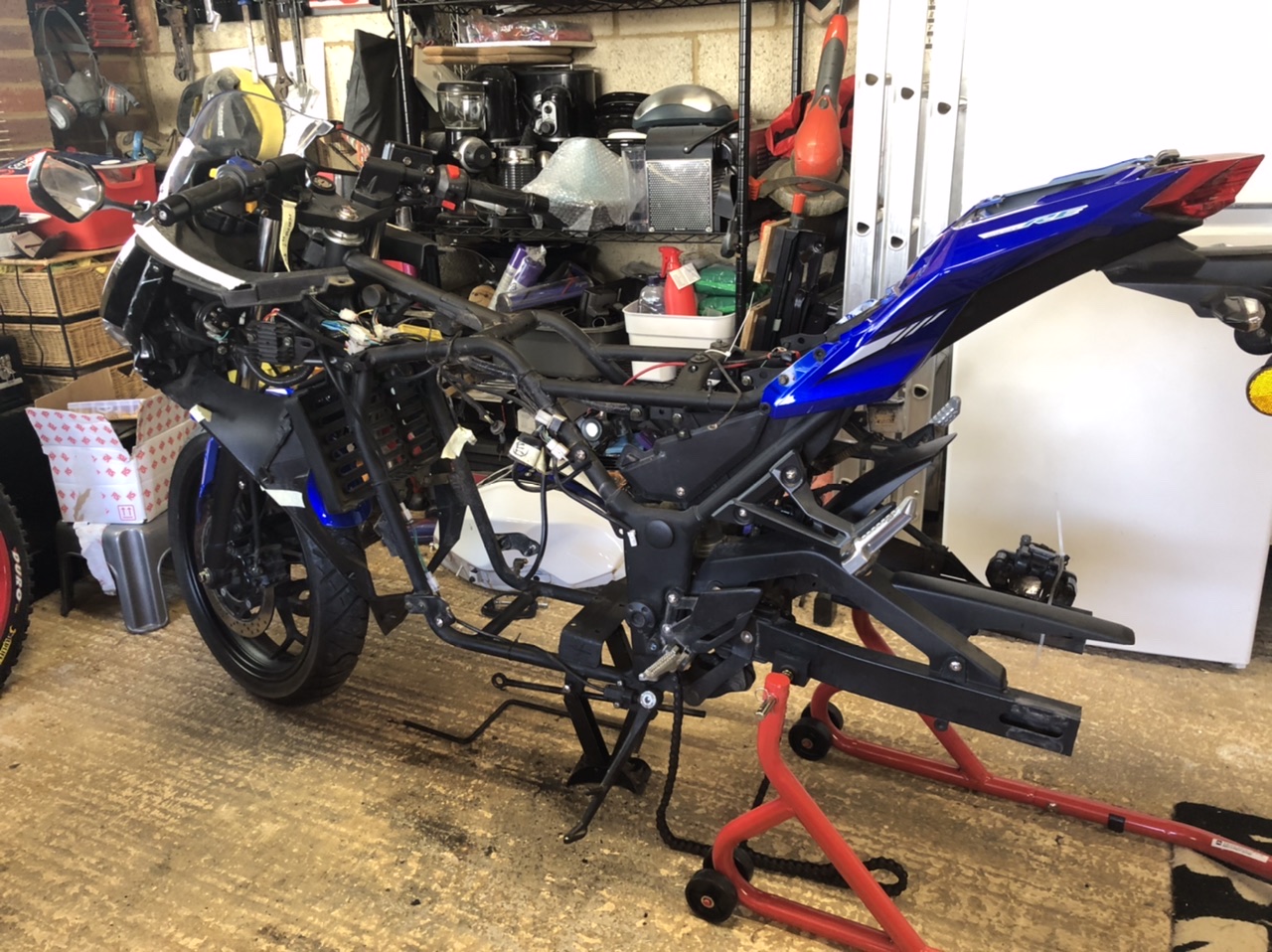
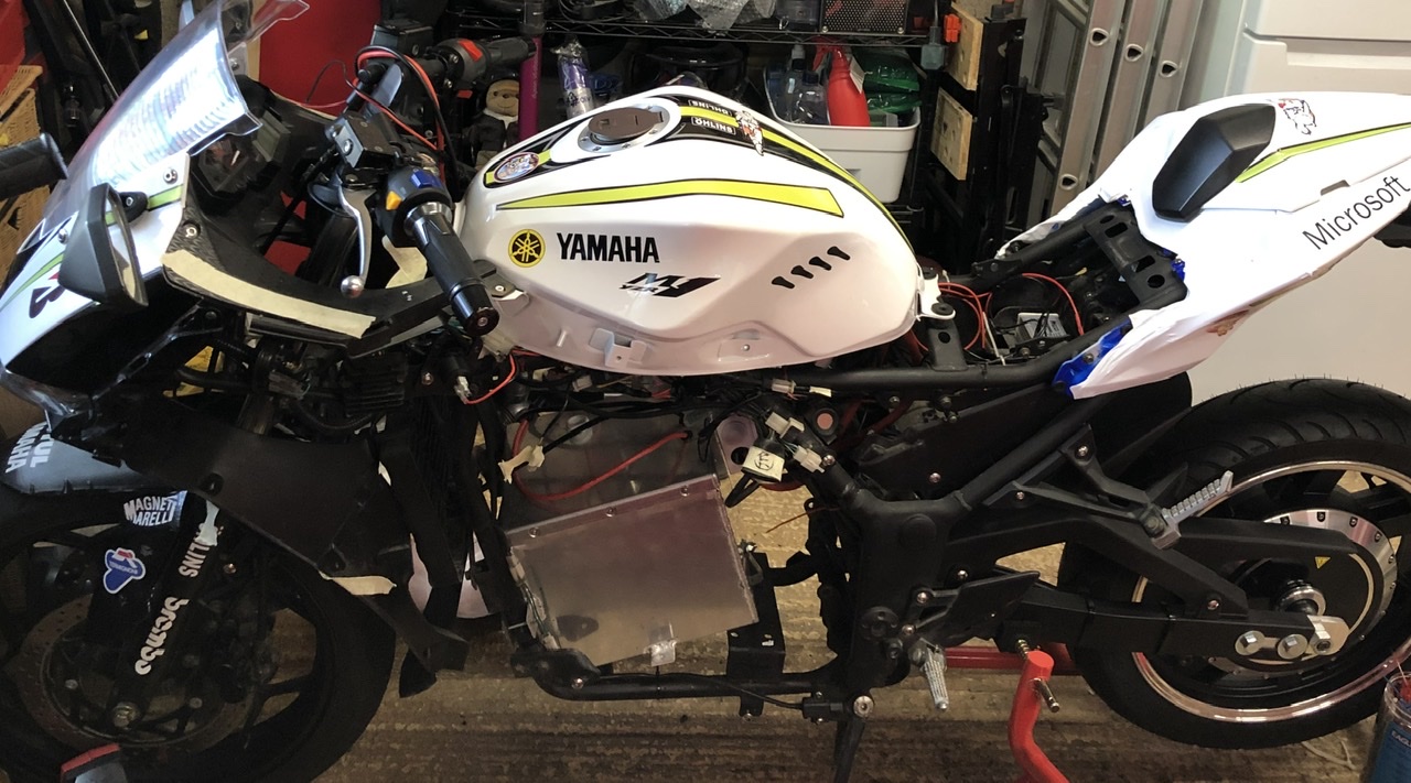
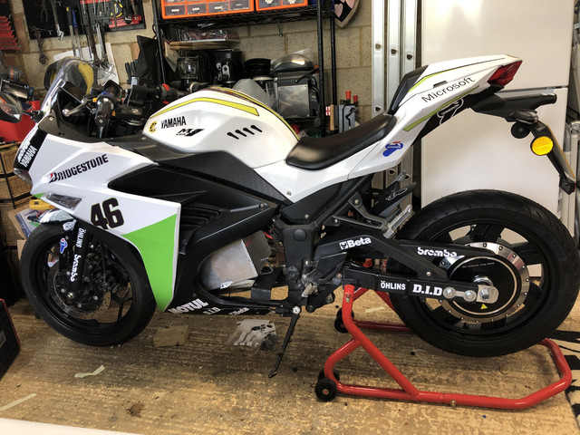
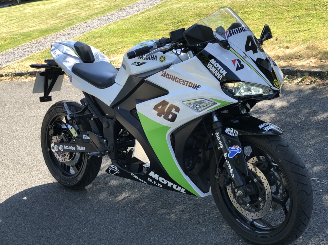
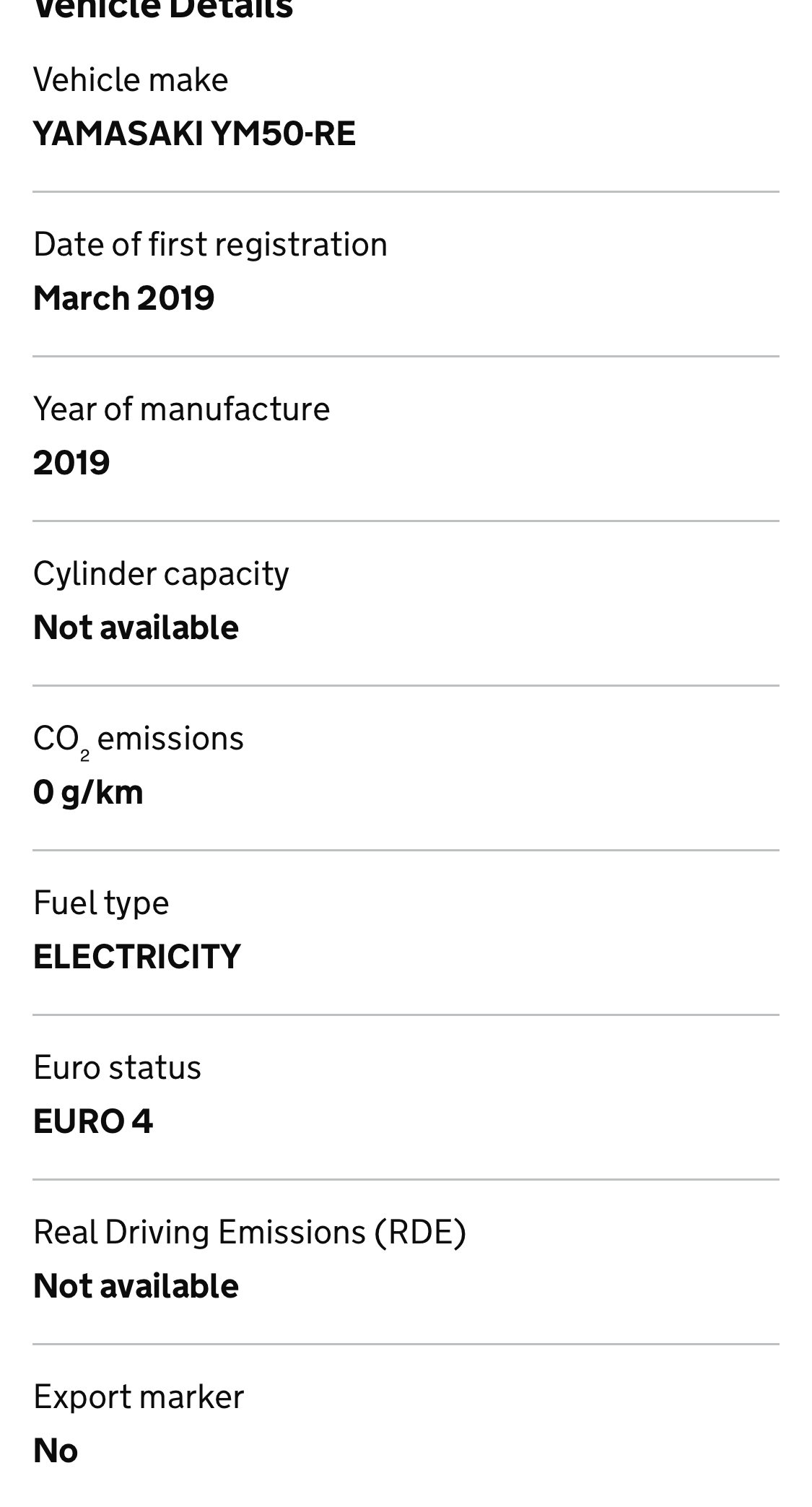
As there’s still some interest in the build from folks here on the forum here is a new thread documenting it from the beginning, this time using a new donor bike, a Yamasaki YM50-RE.

CA9692-EE-1-EB5-4-AF4-A1-C7-14-C0-A98212-D5.jpg


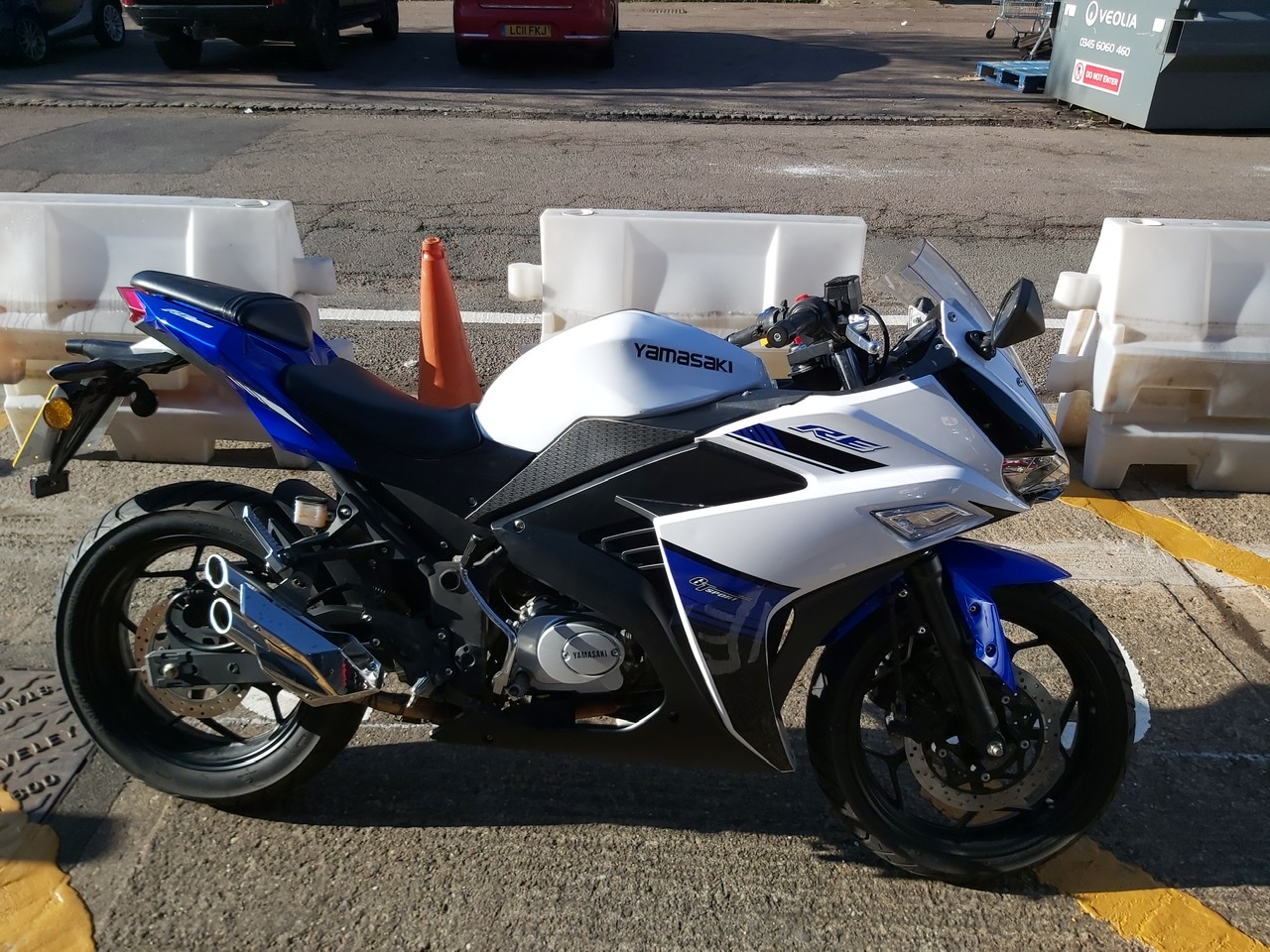
This is a Chinese Yamaha R3 clone imported to the UK, using a pretty generic frame and 50cc pitbike engine. It’s very similar to the base bike from companies like Hanbird selling Chinese Electric Motorcycles with hub motors from QSMotor of various ratings. I had originally looked at importing one of these to the UK but when I went into it, and the challenges of getting it through an MSVA test to be roadworthy, the cost and effort wasn’t worth it.

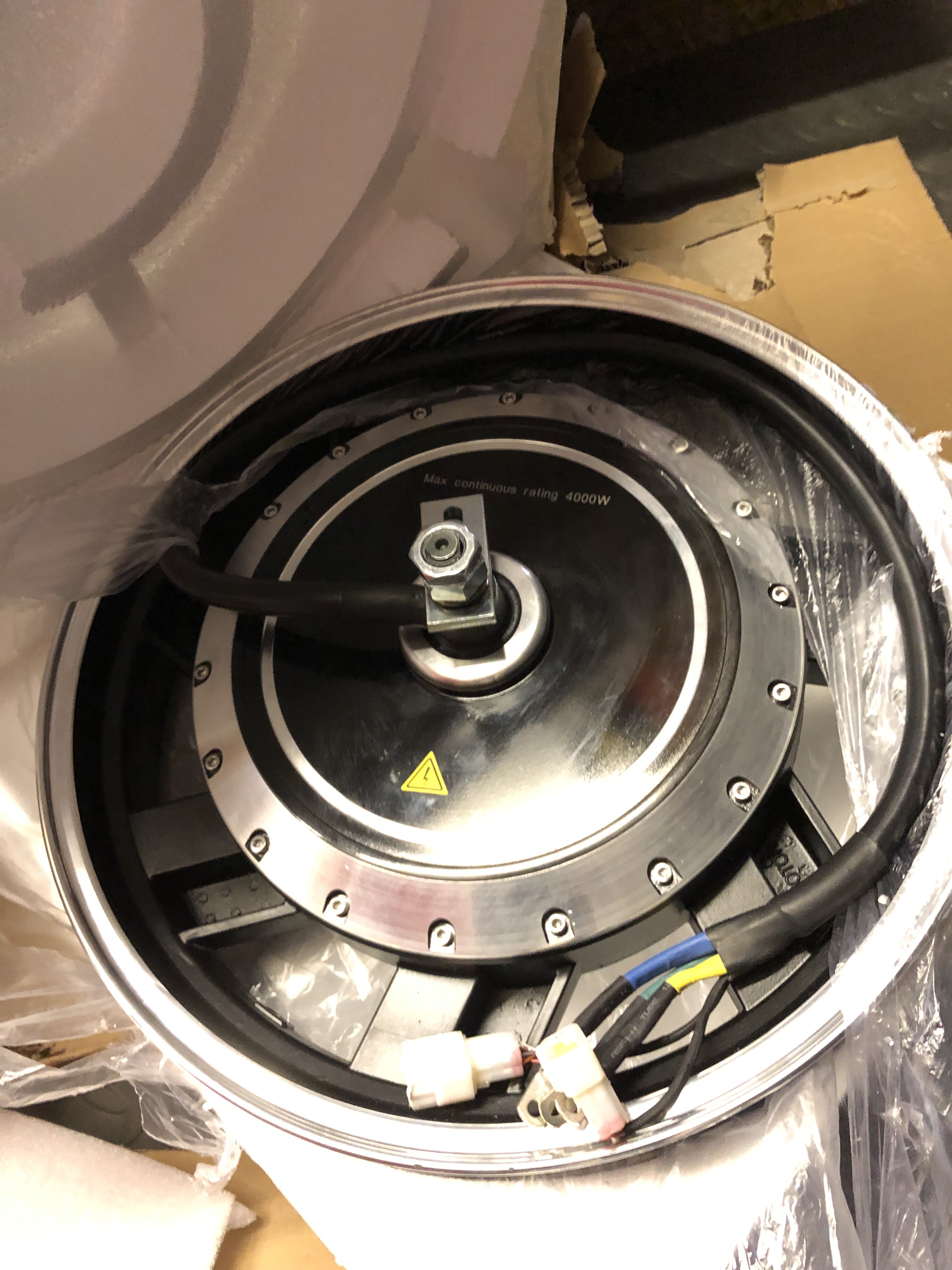
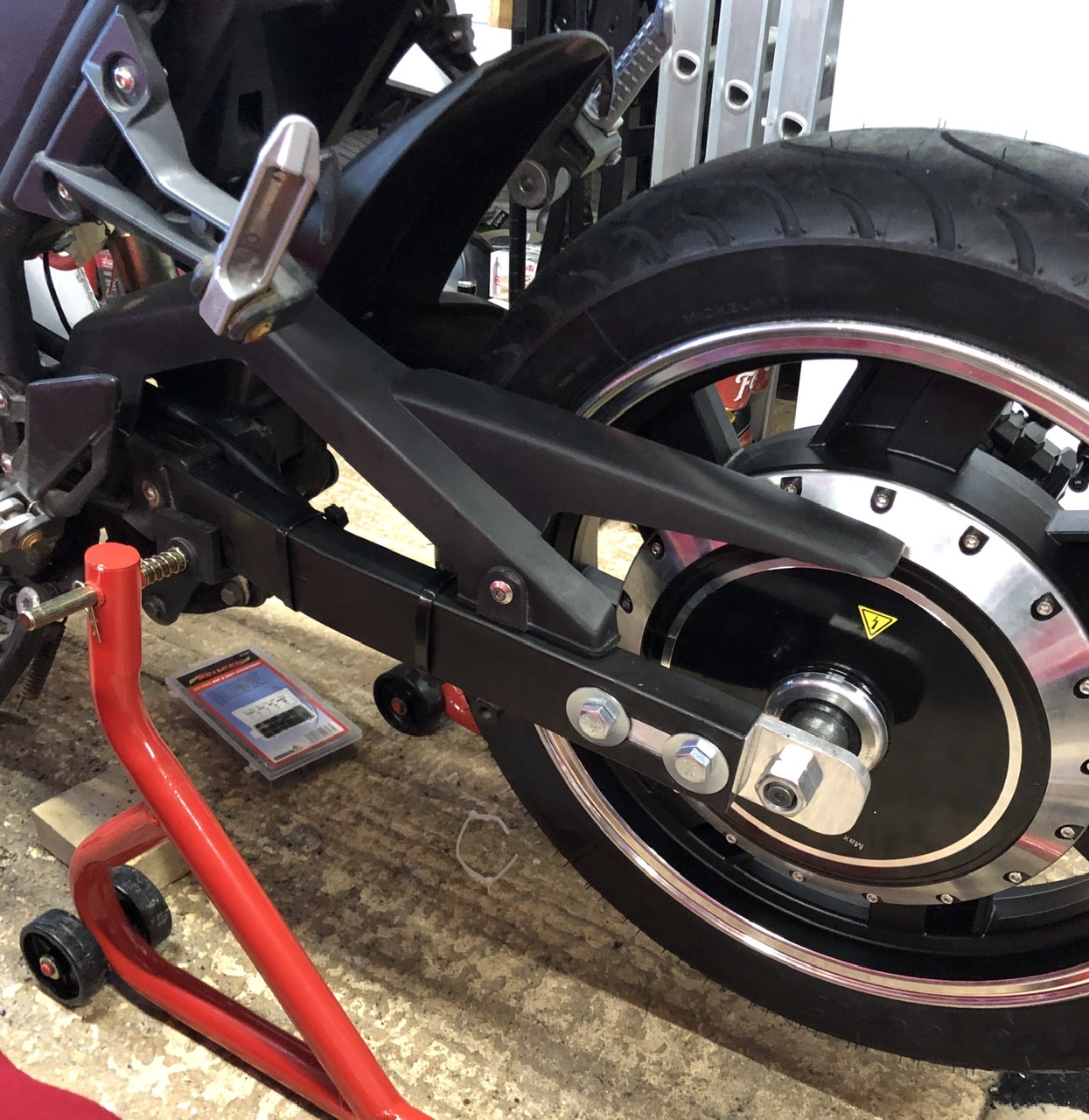
I decided I would keep the EV conversion as a 50cc/moped as in the UK this is just a matter of registering the change from petrol to EV with the DVLA and having the necessary paperwork demonstrating the power of the motor. In some cases an engineer report is also required. So this meant a hub motor with continuous power rating of 4000w or less.

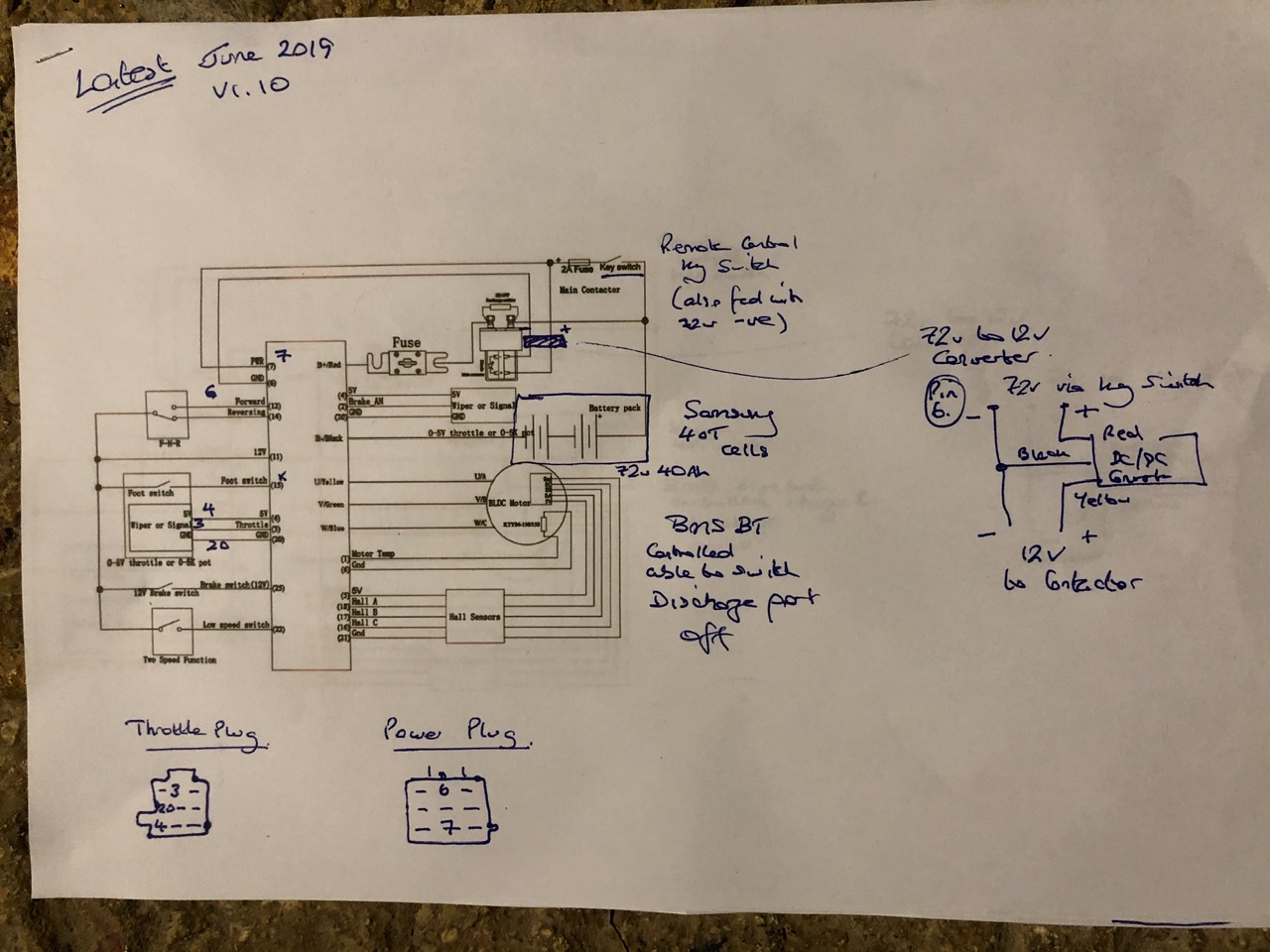
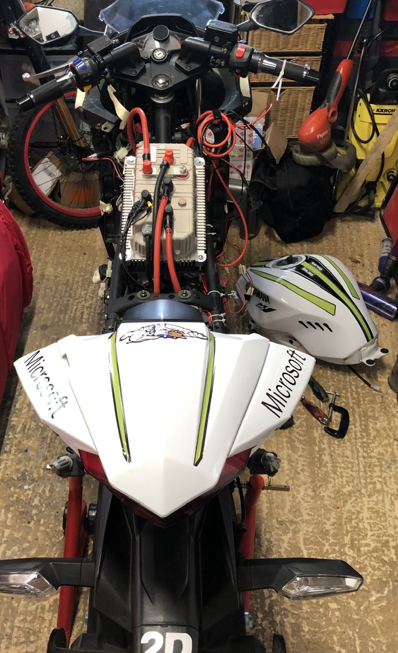
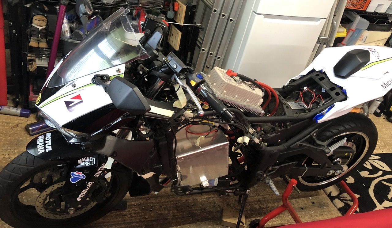
Having decided on a hub motor set up I went for the following motor/controller/battery spec:

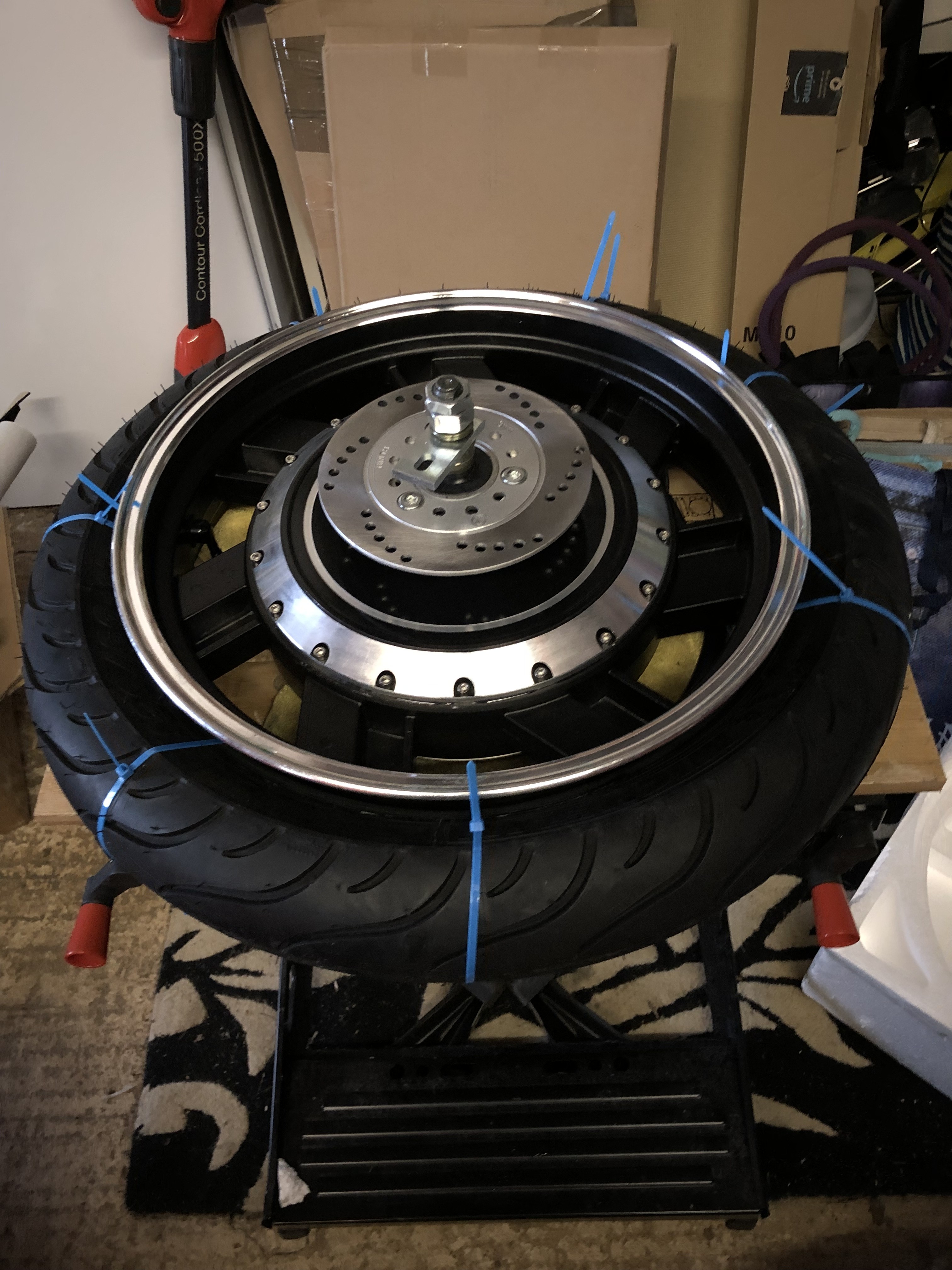
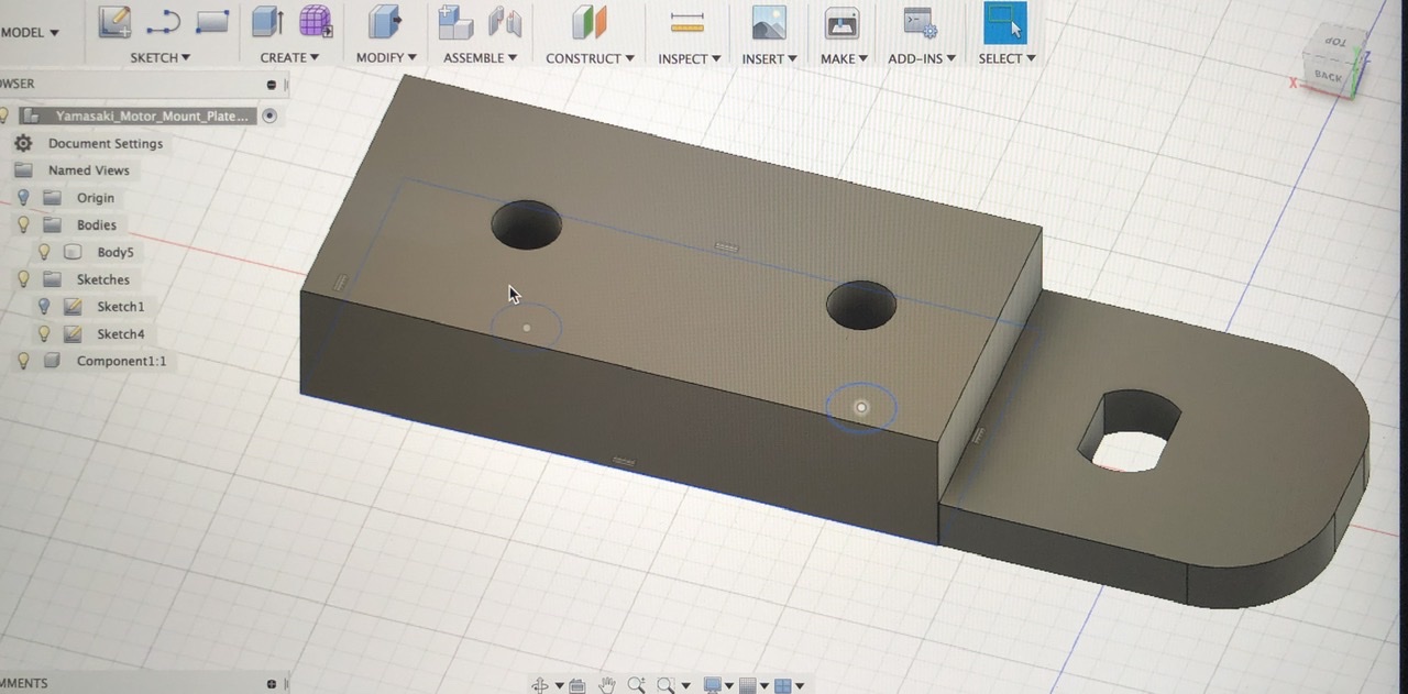
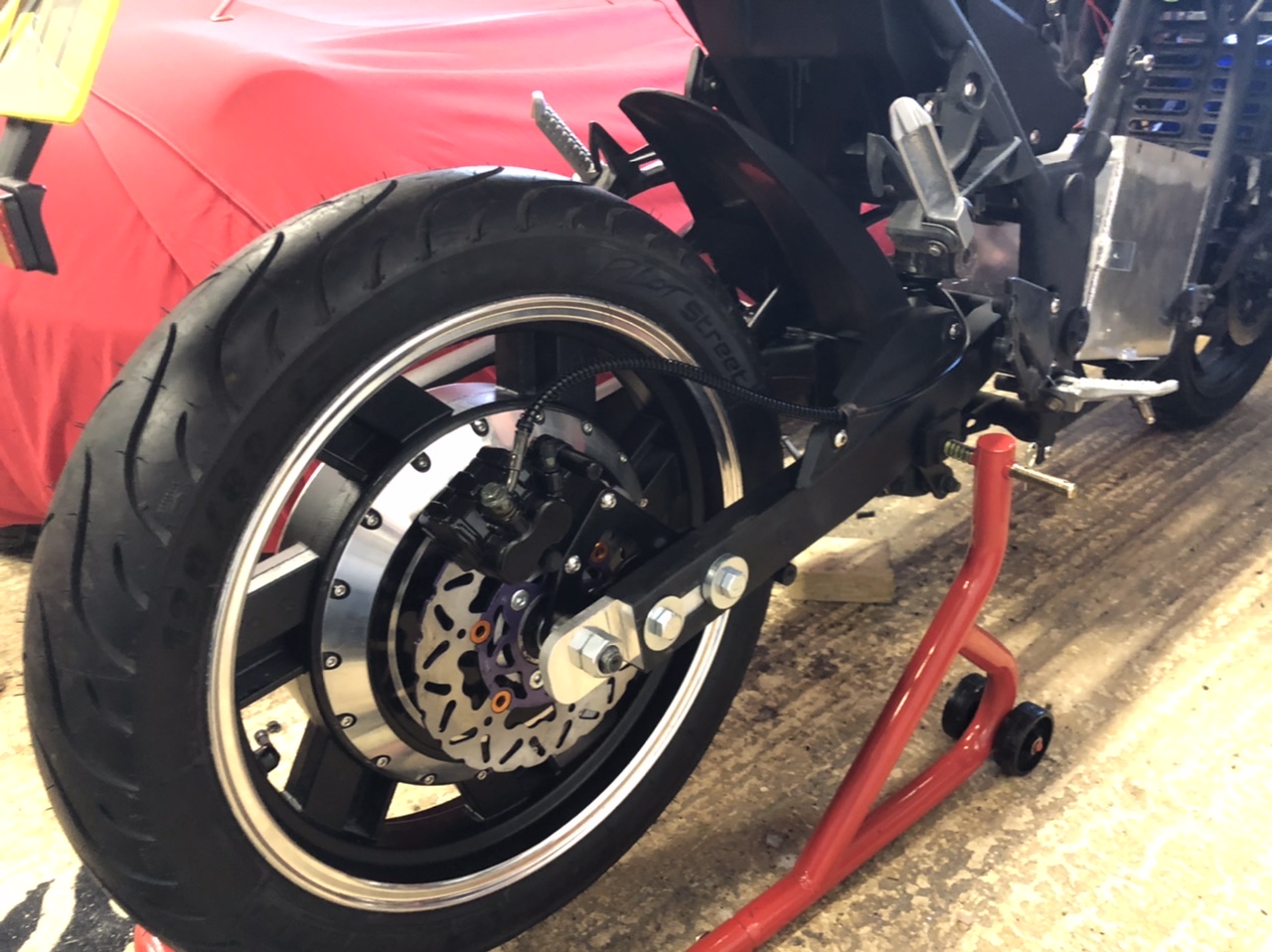
QS Motor V3 17” 4000w v3
Kelly KLS7275H
Custom 72v 40Ah 20s10p pack using Samsung 40T cells
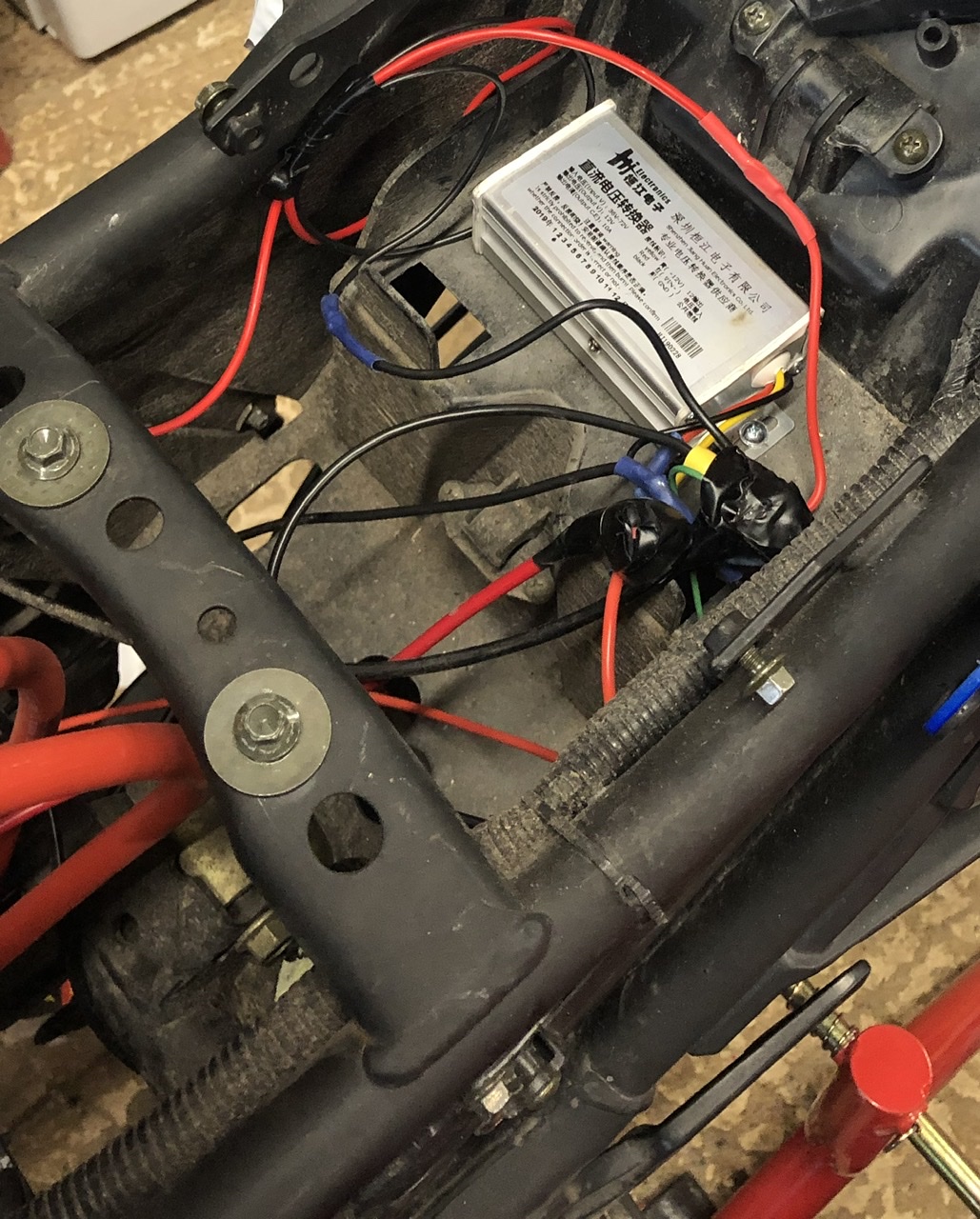
Smart Bluetooth BMS capable of 160A continuous 320A peak
 
Motor and controller arrived back in May 2019, and first step was to get a tyre fitted to the hub motor.

9-E863-BDF-0230-4510-BE26-D68-C876-EC073.jpg


No motorcycle shop or tyre fitter would touch the hub motor in terms of getting a tyre fitted so I did this myself. I used the cable tie method to get this onto the hub motor rim, and then removed the valve core to use a couple of good blasts of compressed air to seat the bead of the tyre all the way around the rim. Seems to be seated OK and holding pressure fine. I can recommend using a Black and Decker workmate bench for mounting the hub motor rim on to make this a lot easier!

86250432-991-A-4022-AE45-7-F1-EDA87-BFA6.jpg


I designed an aluminium enclosure for the battery pack to provide some level of protection, and had this welded/fabricated.

679-BE6-C5-9-E4-E-4-EE8-811-B-C5961-BB3066-E.jpg


Other projects and life overtook things then until later on in 2019 when with the custom battery built I set about wiring everything up off the bike to bench test the set up.
 
I decided to ditch the 12v battery on the bike completely and just use the 72v pack, with a convertor to step this down to 12v to power the lights, indicators etc.

I’d been gifted an as new contactor (Tyco Kilovac EV200AAANA) with suitable pre-charge resistor, only to discover that this needed 12v to operate the solenoid, so a second 72v to 12v convertor was included in the configuration to drive this.

Having studied the Kelly KLS7275H wiring diagram, I confirmed with Kelly that pin 7 does require the full 72v voltage (not 12v as some sources suggested).

The Bluetooth enabled smart BMS came with an Android app that I planned to use with a smartphone configured for the bike, and this would be used to switch the discharge side of the BMS on/off as a pseudo master switch. I also included a second master/kill switch in the wiring set up that has a remote control switch.

Throttle (I’m just using the one supplied with the motor and controller for now) was wired up and I ended up with the following set up.

63-F9-BF74-0301-4008-BA08-E8-DC1-C916-ED5.jpg


I mounted the wheel in a test jig made using a paddock stand and the identification angle process worked first time using the Kelly Android app. I had to switch the direction of the wheel but otherwise everything worked fine.
 
With everything working off the bike I then began the strip down of the Yamasaki which went without any issues, and I soon had pretty much a bare frame.

09-D2-FAC8-5043-42-F0-B3-A8-59215-B3-CEE81.jpg


My original plan had been to cut slots at the rear of the swing arm to slot the fixed axle hub motor into. However, as the Yamasaki swing arm is made of box section the axle wasn’t actually wide enough to be able to fix the nuts to without cutting a large recess into the box section, which in turn would have weakened the swing arm. I was also wary of cutting the swing arm at all as I know the DVLA in the UK are tightening up on what mods you can do to frames and swing arms for EV conversions.

Having looked at a couple of other hub motor conversions on the ES forum I came up with the following design for a set of adapter plates each side of the swing arm that would slot into the box section and bolt through the existing axle cut out in the swing arm. These were designed in Fusion 360 and then fabricated in T6061 aluminium.

36-C4-DF0-C-5420-4563-815-E-C0598-B9111-B0.jpg


I took some advice on designing the plates with the axle flat vertical rather than horizontal in terms of loads on the plate, plus I wanted the phase wires to exit the hub motor and run along the swing arm.

D3335-BEA-5-A14-4-D4-C-B824-E6-A24015-D2-A9.jpg


I’ve already had some feedback that this may not be the best design for durability, given the risk of the hub motor axle cutting into the aluminium. I’m comfortable with the approach given the torque figures from the 4000w motor and the fact I”m not going to be pulling more than 150A from the pack, but I’ll keep a close eye on this and mark up the axle nuts so I can spot any movement in them on the road.

C0-DCD765-4892-47-C8-9-F35-823-ABAD90024.jpg


I decided to convert the rear brake set up to a handle bar operated lever in place of the now redundant clutch lever. The motor/controller kit came with a caliper and lever/reservoir which I was able to use, sourcing a larger brake disc (220mm dia) in order for the geometry to work with the brake caliper and mounting bracket.

Throttle is now mounted, and the next step (which is where I am as of today) is to fix the controller and battery box. You can see roughly where the battery box will be mounted on the picture above, and the controller will be mounted to the frame under the gas tank, which will have the base cut out.
 
Hi swiftyds

That's a nice looking donor and decent frame design. Looks good.

Please consider my comments to Lightrule about the swingarm blocks, unless there is another torque limiting bracket with the motor. I possibly noticed something in one of your guys' pics that might be it but it looked SMALL and underwhelming...

Cheers
Tyler

 
This is the images I mean. Those small brackets behind the nut on the axle. How will you secure these to the swingarm?

Edit: link didn't work. One of your last posts with pics in old thread, showing motor with tyre on..

Cheers
Tyler


Hi Tyler - yes the hub motor is supplied with very small torque plates for each side - I’ve seen these used on lower power (up to 5,000 watt) bikes sold out of China where the swing arm width is narrow enough so these bolt to the swingarm sides.

I’m currently making up a clamp bracket for the side of the motor where the phase wires exit so I can clamp into the thicker part of the axle flat. This will then bolt to the adapter plate I’ve had fabricated on that side of the wheel.

Agree I could have made stepped adapter plates for the swingarm to remove the need for this but have taken advice from others on the forum about a clamp arrangement being stronger longer term.
 
Alongside sorting out a better torque arm clamp for the hub motor I’ve been focusing on getting the controller and battery/box mounted in the frame.

Controller fits perfectly on the frame under the tank leaving plenty of surface area free under the heat sink.

490412-A8-8-BB8-4-D9-C-874-B-363-E6-C8-F63-E0.jpg


NOTE: Positive wire for 72v battery feed on the wrong end of the fuse here in the picture!

I’ve also done a bit of wrapping on some of the plastics to do a bit of a colour change and jazzed the tank up - too much time on my hands during lockdown!

The battery box is secured to the frame in the area where the dummy radiator vent is in the plastics and then with a support bracket at the back of the box as you look at it in the picture below which bolts to one of the engine mount holes.

13-C66-A33-946-D-4-CE7-9-DAC-32-A28339-DD78.jpg


Battery was secured in the box itself with dense foam and packed all round inside together with the base and lid area.

I’m using two 72v to 12v converters - one to step down for the solenoid on the contactor (which is 12v) and the other for the 12v circuit on the bike (lights, speedo, USB charger etc). One is mounted behind the battery box the other under the seat area.

F246-C252-2-E64-4-BCE-8728-F382-BBD55-F8-E.jpg


I’m about 95% of the way there securing all the wiring on the frame. By chance there was a spare bracket below the controller on the frame that was the exact size for mounting the contactor - how lucky was that! Less lucky was that the phase wires from the hub motor were about 10cm too short to reach the terminal posts on the controller - I fabricated a junction box and had a set of cables made up to extend the wiring - unfortunately I could only get these made up in red and black - would have looked better to have them in yellow, green and blue. The junction box is mounted the rear of the battery box and is waterproof.

The phase wire cable is now mounted and secured to the swingarm.

654-B4-B28-4-C1-B-4-AD5-BB24-0-E07-FD9-B6-FD8.jpg


I also wired in the rear brake switch from what is now the handle bar mounted lever.

Next job is to check and double check all the wiring and phase wire junction box before powering everything on for what will be the first trial with everything mounted on the frame itself.
 
Very nice progress. I understand about the torque arms, look forward to seeing what you use.

Cheers
Tyler

 
Decided to push and cut the bottom of the petrol tank out and check the tank would fit over the controller and wiring before connecting everything up and doing a full test.

Plenty of room under the tank and didn’t take too long to cut out a large enough area in the base of the tank.

7-DF79-F16-A786-4-FEA-A997-A7348-E53-D792.jpg


Fits perfectly over the controller using the existing mounting points. I used a rubber edging strip around the inner edge of the cut in the tank just to be safe if anything rubbed against it.

You can see a bit more here of the vinyl/stickers being used as part of the conversion.

8-A655-D51-192-F-4982-924-B-A647-BD3362-A5.jpg
 
I was asked to post a picture of the fuel tank with the rubber strip applied to the area of the metal that was cut.


Before fitting I painted the inside with black paint to hopefully prevent rust.

Once the tank was secured I checked all the wiring over and ran through a couple of tests of the battery and controller. All with the bike on the paddock stand and everything worked great. I realised I hadn’t done anything about the electronic fuel gauge on the digital dash of the donor bike which was flashing empty - very annoying. To prevent the flashing I wired in a 10ohm resistor to mimic the tank being full.


Before refitting all the fairings there were a couple of panels I hadn’t wrapped white, and I also wasn’t happy with the chrome rim of the QS Motor hub which stands out against the Matt black of the wheel so decided I would paint this Matt black. I used a combined primer and paint in one and apart from a little rubbing down with wet and dry it applies with a brush and the results are really good - almost indistinguishable from the black on the wheel itself.


Small thing and little effort but seems to make a huge difference in overall look!

That just left the fairings and plastics to refit to the frame. Just about there now and pretty pleased with the end result ...


Hard to believe it started out as this .....


And now is this....


Need to lose the reflectors on the tail tidy and can’t decide if I want/need to put a plastic panel on the inner edge of the fairing where the motor was and where you can see part of the battery box to hide this?

Lockdown in the UK means it’s not easy to test it out on the roads so a bit more tuning of battery and controller on the paddock stand in the garage for now.
 
Spent a bit of time today adjusting battery and controller settings. For controller I’m using the Kelly app on Android. Main settings I’ve been playing about with are:

Max speed 8,000 (factory 4,000)
MidSpeed Forw Speed 100 (factory 50)
Current Percent 100
Battery current limit 50
Accel time 3 (factory 10)

Discovered importance of MidSpeed figure as I’m not using a 3 speed switch in my set up.

It’s a 200A (phase amps) controller with claimed bursts up to 500A and my battery can pull bursts of 160A so there’s more I can play with on the current and battery % settings.

Looking good so far with unloaded testing on the paddock stand ....

https://youtu.be/v9-wGhXBRYQ

One thing that is puzzling me with the Kelly app - In the monitoring section the Motor Speed value is documented as being motor RPM (same as the Max Speed setting). However at close to full throttle I’m seeing a figure here of over 5,000 which can’t be RPM otherwise my bike, albeit unloaded on the paddock stand, would be doing over 300mph! So it can’t be RPM and I’ve set the correct number of poles for the motor in the app.

Anyone have any idea what this figure is actually based on?
 
Managed to sort this - although I had changed the poles setting in the Kelly app for some reason it wasn’t writing the update back to the controller.

Sorted now and max RPM unloaded on a paddock stand in the garage is around 1150 which is about right for max of the 4Kw motor with the battery and controller settings I’ve got set.

Still need to give it a decent run out on the road to see what actual max speed is.
 
Hi, did you get to road test the bike in the end. Really impressed by the project and curious how it worked out.

Could you explain why the rs50 swing arm did not work, surely all these bikes have the same width axle space
 
richardab1967 said:
Hi, did you get to road test the bike in the end. Really impressed by the project and curious how it worked out.

Could you explain why the rs50 swing arm did not work, surely all these bikes have the same width axle space

Yes managed to get it out for a couple of road tests now. Performance is great - much better initial acceleration and pick up. Need to give it a longer run but still checking everything is OK post the build.

Here’s a short video of initial test ride ... quality not great!

https://youtu.be/Uca-Xoost4k

I’ve also gone through all the paper work/registration changes with the DVLA to change it from petrol to electric - with Covid 19 the paper work is still with the DVLA.

Will get a better walk round video up on YouTube going through the components, and hope to get a few more longer runs in. DVLA have said it’s OK to be using it on the road whilst paper work is processed as it’s already taxed/insured and MOT not due for another 2 years.

72-C3-F9-CF-E2-AE-440-E-830-A-20520-ADE17-D2.jpg


I’ve been surprised how many folks who’ve seen it think it’s a professional/production spec electric motorbike. And those who know their petrol bikes really think it’s based on a Yamaha R3....not a cheap china clone (Yamasaki) - well pleased.

Another thing I’m surprised at is just how quiet the hub motor is even at speed. I’m used to more motor sound with the eBikes I’ve built with hub motors but this thing is so quiet. So much so I’ve started looking into building some form of synthesised engine simulator sound module. Bit more work needed on that...

Issue with the RS50 swingarm was that it was a 99-05 model so rear width for axle/drop out was only around 185/190mm. I knew this when I started the build (QSMotor 17” motorcycle wheel hub needs at least 200mm) but believed I could use adapter plates to give me an additional 20mm width. I got as far as getting the wheel mounted but there wasn’t enough clearance to get a brake caliper bracket mounted and all the geometry to work out. I’m sure a post 06 model would have been easier due to wider swingarm but was too difficult to find another swingarm to fit the original RS50 frame I had.

I’ve actually got a spare RS50 frame and swingarm that I ended up buying with V5/plate as part of the build that I keep toying with another build on, this time using a mid-mount QSMotor 4kw motor.
 
Great news that its actually ridable now, congrats.

Amazing that the DVLA are cool about you riding it mid changeover, they are normally a total pain with this sort of thing.

Have to say it looks extremely convincing, initially as a proper sportbike and then when you figure whats going on as a high spec electric bike.

I was looking at the RS50 only as there seem to be a lot more around, in varying states of repair and price. The Yamasaki I guess is a newer bike so less beaters around going cheap. Although the RS50 aluminium frame is probably slicker, I would say the steel tube frame on your Yamasaki probably give more flexibility and space.

I guess having not taken it for a longer run you don't know what real world range your 72v 40ah will give you, do you have an idea?

Keen to give an e-motorbike a go, I have done a couple of e-bikes and am building a petrol kit car at the moment that I will one day want to convert to electric so a motorbike seems like a good step up practice project to learn more.

I like the idea of using a 50cc base, as I (assume you are the same), don't have a bike license. Where there any other base bikes you looked at before finding the RS50 and Yamasaki, I did find some other versions of the RS50, like Derbi GPR and Rieju but they don't seem that common in the UK.

I know the 50cc moped equivalent is 4kw, which i assume you have to prove to the DVLA somehow, how do you 'prove' its limited to 30mph...which I'm sure it is!! :wink:
 
DVLA were quite helpful - I managed to speak to someone there when they weren’t accepting any paperwork due to Covid 19 and got them to record the fact they’d told me it was OK to ride still post conversion as it was MOT’d, taxed and insured.

Looking at the frame, to be honest the Yamasaki was much easier to convert than the Aprilia would have been. OK it’s heavier but it’s also a much bigger bike so can accommodate batteries, controller (the width of the Kelly I used would have been a tight fit under the plastic Aprilia tank cover) and things like contactor, 72v to 12v step down transformer etc.

You do see Yamasaki’s coming up on eBay (in fact there was one up there yesterday but looks to have sold). You can pick up a good year old running bike from the importer who seem to have a good stock as people trade up to 125cc for around £1200 - not many Aprilia RS50s even in project form go for less than £800-900 and by the time you’ve sorted out/serviced all the parts you need to keep post conversion like forks, front brakes, lights/indicators, fairings you’ll probably spend more than that. I looked at most 50cc bikes you can think of ... if I was doing it all again from scratch I’d use the Yamasaki again but probably go with a mid mounted motor.

On range, I’ve not pushed the pack yet but based on short rides of a couple of miles it’s looking like around 45-50 miles will be max range, dropping down to around 35 miles if I push it. Still absolutely fine for what it was designed for and I’ve got space for at least 3x battery capacity in terms of storage in the frame so definitely possible to get 100 mile range if needed.

On the conversion side and registering the change with the DVLA .... 4Kw is the electrical equivalent of a 50cc and the key is that it’s 4kw Continuous. Whilst the motor may be able to peak/do bursts above this it has to be certified to be 4kw continuous. I ensured this was recorded on the invoice from QSMotor and also got a motor number (engine number equivalent) recorded by QS Motor on the invoice which I then had etched onto the motor. QSMotor are really helpful and will etch what ever you want on the motor plate so I also had them record 4000w max continuous on the plate as well. On the accompanying letter to the DVLA along with a couple of photos , updated V5 and invoice for motor I recorded the fact that the petrol engine has been completed removed (seems they can get confused with hybrid conversions when reading the paperwork) and replaced entirely by electric engine. Also no other changes have been made including any changes to top speed ... so it’s still equivalent of restricted 50cc. I have set the controller to limit speed so I can prove 30 mph (28mph) max if needed.

As the paper work is still being processed (I keep checking via the DVLA online vehicle info to see if the change has gone through) it may well be they come back with challenges/questions - most other folks have managed the same conversion OK. They can request an independent assessment by an engineer which is fine if that happens - it’s just a matter of finding someone who can do this and write a short report. I know someone who can do this for me locally who has experience of building/evaluating EVs.

I’ve also built a number of kit cars and quite fancy building an electric reverse trike - started looking at what’s involved in that with MSVA test etc.

I was in same position as not having a bike licence but having rode scooters when I was younger and didn’t want to ride round on L plates on a 125cc equivalent. That said, I will probably take my bike test now.
 
Thanks there so much useful info in that post.

Can i ask why you would consider a mid mount. I had wondered if the weight of a big hubmotor might affect the handling and unsprung weight. But i really like the simplicity and compactness of the hubmotors.

An alternative base bike i have looked at is the very budget lexmoto hunter 50cc. The yamasaki is a wicked looking machine but i was hoping to do something more retro, ie cafe racer, twin shock, spoked rims, and the lexmoto could lend itself more to that look. Need to get close to one and take some measurements of swing arm and engine bay area.
 
Yes you’re right - hub motor much easier. I think if I was building another I fancy keeping rear wheel/brake set up as-is and challenging myself with engineering the motor mount. Would need to be a large-ish bike like the Yamasaki to leave enough room for batteries.

I remember I did look at the Skyteam Ace 50cc as as donor .... I also like the idea of a retro design and with a suitably sized retro race fairing on there would be enough space to hide the batteries. In fact I saw a picture of a similar designed bike, Hammerhead Volta 102, before I started my build which tempted me down the Skyteam route (which in itself is a cheap Chinese clone of the Honda Dream 50). The Hammerhead used an Enertrac hub motor.

FDA3-A30-F-91-FA-4974-9-DFF-F1-C7-CC34-C55-F.jpg


https://evmc2.wordpress.com/2013/11/13/the-electric-garage-hammarhead-volta-102/

4-BD21528-3-E87-4-CFE-BC8-F-0-DE9931180-CE.png
 
Final stage of the process is complete .... the registration changes from petrol to electric were completed yesterday by the DVLA here in the UK. Process went without a hitch - they accepted the paper work and V5 changes I sent through , no need for an inspection.

9679722-F-3274-462-E-B8-A9-55-E7-B68-EC210.jpg
 
Awesome work on the conversion and congratulations on getting it all certified. The bike looks great! Was very impressed with the brackets you’re using to mount the hub motor. I recently converted an 1989 Yamaha FZR250 and ended up cutting the slots in the swingarm to make dropouts and used solid aluminium blocks that clamp onto the axle flats to resist the torque. Reading your thread reminds me that I should check them to see how they’re holding up. Did the certifying people have any issues with the rear wheel moving back a little? I guess it’s not that much but curious if that came up at all. Are you using regen braking at all?
 
soyachips said:
Awesome work on the conversion and congratulations on getting it all certified. The bike looks great! Was very impressed with the brackets you’re using to mount the hub motor. I recently converted an 1989 Yamaha FZR250 and ended up cutting the slots in the swingarm to make dropouts and used solid aluminium blocks that clamp onto the axle flats to resist the torque. Reading your thread reminds me that I should check them to see how they’re holding up. Did the certifying people have any issues with the rear wheel moving back a little? I guess it’s not that much but curious if that came up at all. Are you using regen braking at all?
Thanks for the positive comments. I still need to add a clamping torque arm on the left hand side of the axle (opposite side to disc rotor) but so far I’ve not seen any cuts/eating into the ally plates I had made. I’ve also marked up the axle bolts with a paint line so I can spot any movement/cracks in the paint quickly.

No problems with the extended wheel position in terms of getting the change made over to electric with the DVLA. May throw up some questions when it comes to MOT but the rear light/number plate holder just about still covers the outer edge of the rear wheel. Benefit of using a year old Chinese bike is that the MOT isn’t needed for best part of another 2 years :)

Yes, got the Kelly controller set for regen braking but only on throttle off and really just to mimic engine braking in an ICE bike. IIRC it’s set to 5 - any more and I was putting too many Amps back into the battery when coming off the throttle above 30 mph and was a bit worried I may damage the battery pack. Without it on (set to 0) I found I wasn’t slowing down enough when coming off the throttle and constantly on the front brake.
 
swiftyds said:
NOTE: Positive wire for 72v battery feed on the wrong end of the fuse here in the picture!

I think the way you've got it wired up is correct if you want it to go through the fuse?
 
Appreciate your post. I would appreciate your eyes as a second opinion so that I do not blow my controller. Here's my setup vis-a-vis power: 72V+/GND battery to a male disconnect. This plugs into female disconnect. Female disconnect with 72V+/GND to female QS10 Antispark connector. This plugs into male QS10. Male end of QS10 GND goes to B-; +72V goes to a 300A/72V circuit breaker. 72V from circuit breaker goes to B+. Given my setup, I assume its safe to wire a piece of #12 AWG with a ring connector from B+ directly to Pin 7 and B- directly to Pin 6? Thanks so much; great job!
 
That took care of the power error. The setup in the previous post does the trick without a GND from B-. That is no connection to the GND on Pin 7, just +72V on pin 6 with 22 solid copper wire. However, now I get the error "Read data error" I've tried changing the baud rate, but then I get "Does not support this model, please choose the right software". Does anyone know the proper Bits per Second, Data Bits, Parity, Stop Bits and Flow Control? Thanks for the help.
 
Back
Top