bluetooth BMS?

rolf_w said:
For a 22s arrangement you need to short 8 cell inputs - you have several possibilities to do this e.g. keep it symetric and short 4 cell inputs on each chip to have them configured as "11 Cells" units (check it out in the table). In your current configuration remove the short between BC7-BC8 and BC22-BC23.

Unforutnately, it does not seem to work. After modifying the solder joints, reorganising the cables and resetting the BMS to 22S mode, the cell 11 reads near zero Volts. The reading of the other 21 cells seems correct. I have to check the datasheet, if the table is valid also for a daisy chainded bq AFEs.
 
Inwo said:
Got a new rca tablet. Still can't connect bms or vbms.
I did get HYD to connect. I like that better in any case.
The Chinese version always connects, but has other issues.

I may have an explanation for you. My new phone won't connect either, but my old phone works fine. I think there must be some BT technology differences here that are making new tech NOT work with older BT tech in the BMS's. My new phone while all up-to-date tech is fast and works great, it also doesn't like older BT stuff. There's more than one thing I have that work fine with my old phone and don't with the new one. I bet that's your issue.
 
ctirad said:
rolf_w said:
For a 22s arrangement you need to short 8 cell inputs - you have several possibilities to do this e.g. keep it symetric and short 4 cell inputs on each chip to have them configured as "11 Cells" units (check it out in the table). In your current configuration remove the short between BC7-BC8 and BC22-BC23.

Unforutnately, it does not seem to work. After modifying the solder joints, reorganising the cables and resetting the BMS to 22S mode, the cell 11 reads near zero Volts. The reading of the other 21 cells seems correct. I have to check the datasheet, if the table is valid also for a daisy chainded bq AFEs.

Hmmm...perhaps this channel is dead in the BMS? I'm skeptical, but new electronics do fail from time to time.
 
The channel is fine, when I set 26s to 30s, I can see all 22 values.
I think that 22s is not divided as 11s + 11s between the AFEs, but rather 12s + 10s. I'm going to figure it out.

EDIT: OK, tested. For 22s, the first half (from the B-) has to be configured as 12s and the second half aos 10s.
 
Well truly massive disappointment today.
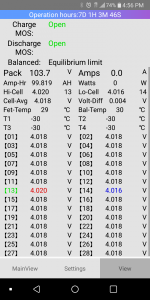
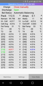
Ran the balance mode yesterday to balance the cells and everything worked great. Balance mode worked to within .01V as set on VBMS app. All VBMS info showing up on my phone nicely.
Getting psyched to charge and go for a ride.
I went to charge the battery and things got real ugly.
My charger is 42volts-2 amps.
Put multimeter on the charger and it reads 42 volts so all is good with charger.
10s (liIon samsung18650 cells) battery so I should be good with that to charge up to 42 volts.
All settings correct on VBMS Bluetooth app for 4.2 volts charge to each cell so I should be fine. All sense leads work perfectly and return voltages for all cells properly as balancing mode was spot on with no problems.
I connected the charger turned on and then:
First thing I get on VBMS screen is MOSFET anomaly in red. Then cell voltage warnings with 4.45volts in red on cells 1 and 10 spiking compared to rest of the cells which were all lower voltage.
If I let it continue, it will charge for a while at 1.5 amps but then the amps slowly go down, and eventually the BMS shuts off cell balancing (says balance limit-prolly due to large difference between voltages on the cells (1/10) and all the others which seem to be charging OK) and then the charger goes to green and shuts off because the BMS shuts down the balancing?
The first cell with the positive lead on it charges up way too fast with voltage spiking at (4.45 volts) and the last cell with the b-lead from BMS does the same thing (4.45 volts). Cells 1 and 10 are getting way more voltage/charging way faster than all the others? Something is funny in that the first and last cells are charging up way faster/taking way more voltage than the others in the 10s series?
So the battery is getting out of balance even with the couple minutes of charging it gets before everything shuts off. Cells 1/10 going up in voltage way too fast, all other cells seem ok.
Reboot VBMS, everything seems good. Then try to charge, same thing again.
Not happy at all. I really wanted to go for a ride today.
Any ideas?
I'm thinking the charging part of the BMS board is bad because of the MOSFET anomaly warning? If so, I wasted a lot of money and time on this Bluetooth BMS project.
 
Can you post a pic of the battery? The only way some cells charge faster than others is if you have cells of different capacity.
 
All cells are brand new.
Photo of battery on end of page 29 of this thread and a closeup a few responses up from that on same page.
 
Pretty unlikely the first and last cells are bad or charging faster.
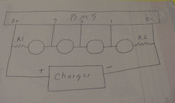
Look for common impedance in the power wiring and balance leads.
R1 and R2 will make first and last read high.
common impedance.gif
 
check the balance wires. especially the first and last 2. remember that the first - side has to go directly from the battery terminal to the - balance connector as well as the mosfet board. they need to be 2 seprate wires comin from the mosfet board and another for the balance connector. on the end you need a additional wire (so 2 red ones), one just goes in its its normal balance connector position and another wire goes to the last possible connection at the end of the balance connectors.
 
flippy said:
check the balance wires. especially the first and last 2. remember that the first - side has to go directly from the battery terminal to the - balance connector as well as the mosfet board. they need to be 2 seprate wires comin from the mosfet board and another for the balance connector. on the end you need a additional wire (so 2 red ones), one just goes in its its normal balance connector position and another wire goes to the last possible connection at the end of the balance connectors.

I'm still convinced he has something miswired.
 
Somebody knows how to connect the JBDTools program via bluetooth in Windows 10? I want to leave the bluetooth module well packed inside a battery cover. Don't want to lose the capability of using JBDtools to have 100% programmability. I've tried the usual windows "COM" port creation with bluetooth but this module does not work that way. Somebody have tried? suceed? on this?
To be more specific: we need windows 10 to see this bluetooth module as a "COM" port so JBDtools program can open this port and do the usual byte handshake. Of course you need a laptop or PC with bluetooth capability, or bluetooth USB dongle.

Thanks.
 
ElectricGod said:
I'm still convinced he has something miswired.
my guess as well, most mistakes are made at the beginning or end.
 
trazor said:
Somebody knows how to connect the JBDTools program via bluetooth in Windows 10? I want to leave the bluetooth module well packed inside a battery cover. Don't want to lose the capability of using JBDtools to have 100% programmability. I've tried the usual windows "COM" port creation with bluetooth but this module does not work that way. Somebody have tried? suceed? on this?
To be more specific: we need windows 10 to see this bluetooth module as a "COM" port so JBDtools program can open this port and do the usual byte handshake. Of course you need a laptop or PC with bluetooth capability, or bluetooth USB dongle.

Thanks.

I think I tried that too and BT would only work with the android app. USB worked with windows/JBDtools becasue the USB adapter is USB to COM. Usually BT devices do not look like COM ports to windows. For example, I just paired my android phone to my windows PC. It's listed as a BT device, but no COM port.

Honestly though...how often do you really need 100% control of the BMS? I'd say less often than you think. When you've done a test run and are back at your desk and can plug in USB, that's when you might need "full control". IMHO...I use JBDtools rarely...essentially when I need to make a special change. Otherwise the android app does OK. When I do a BMS upgrade and check the shunt resistance, I'll find that despite using the same number and value of shunts that resistance has gone down anyway. This is probably due to significantly better soldering when I'm done than what comes from the factory. I'll change the resistor value to match what I measure on my micro-ohm meter. I've changed cell count and pack OVP and UVP before, but that's about it.

JBDTools%20-%20other%20settings.png
 
Took a little break from this as I was irritated with it-but now I'm back.
My battery is 10s. Total 38.6 V currently. Approx 3.8 V per cell.
Today, I opened the battery back up.
Also took the cover off the BMS again.
The 10th jst pin location shows a red led light on the board. (Photo attached below)
This is the cell group that the VBMS bluetooth program says goes into cell overload immediately when turning on the charger, then it tries to shut everything down? Obviously something is up at this 10th jst location?
Mutimeter from actual battery minus to back of 10th jst plug gives correct voltage of 38.6v (Same as for total battery minus from plus to minus on last cells of battery itself 38.6V)-as it should be.
Multimeter from battery minus to back of 9th jst gives 35V as it should be.
BUT:
From C- pad to back of 10th jst connector is only 18.2V? Should be 38.6V like it is from battery minus.
C-pad to back of 9th jst connector gives 35V (as it should be).
Also from C- pad to to total battery plus is just 35V? Missing a whole cell group of approx 3.8V somehow.
So, I assume something is screwed up between the correct total actual battery voltage and the 10th jst electronics on the board to cause the BMS to be confused. It is not seeing the total voltage of 10 cells as it should during the charging.
It is only seeing 9 cells from the C-.
The 10th jst location has an issue somehow between the correct total voltage presented at the back of the jst in relation to b- (38.6V) CORRRCT and the voltage presented to the c-pad (18.2V) INCORRECT.
I guess the board is bad and I didnt catch it cause I didnt try charging it till I put the BMS cover back on and sealed everthing up?
Lesson learned, always run through all the functions before sealing it up.
Ant other thoughts about this before I try to contact the seller to swap it out for another one?
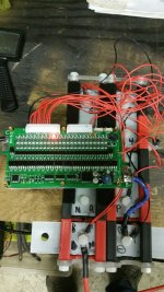
Bluetooth BMS issue.jpg
 
always measure from B-. C- is controlled my the board. when a failt happens it only allows the precharge circuit to pass power.

if the led is lit on the board the it means it is trying to discharge the cell due to overcharging.
measure from the first black wire and make sure to measure 3.8v on each of the balance leads going into the board until you get to the final one. number 10 and the last one should measure identical. also make sure you did not skip a cell.
 
Appreciate your feedback.
All the cells go up correctly from 1s to 10s in approx 3.8V increments from b-0 as they should up to 38V. The last cell 10 is 38V and the second wire from b+ to power the mother board is the same 38V.
I think you may be talking about a different BMS board related to the led light behavior?
On this board, the behavior of the led lights is to be flashing depending on which cell group is discharging. I can see with the app on and with the led lights flashing that the proper cell groups are discharging. The number 10 cell group does not flash like the others--it stays lit continuously (not flashing)-even when the BMS is turned off. It is the only one that does this. Also, as I said previously, the app threw a red MOSFET code when charging previously?
To me, it seems like a fault code since it is not flashing like the others to indicate discharge? But since there is no manual to describe the fault code behaviors I do not know what the continuous led light on at cell group 10 means.
All the other flashing LEDs indicating discharge turn off when the BMS is turned off.
This is the only light that stays on after the BMS is turned off?
I am at the limit of my diagnostic capabilities. I don't know how to analyze the board components themselves and I am not personally interested in learning how to do that.

I am going to order a different charger and different BMS to see what happens with different components.
 
Mikebike said:
I am going to order a different charger and different BMS to see what happens with different components.

Maybe get a different BMS, but hold off with the charger. It's unlikely to be the issue if it is delivering the correct voltage.

PM sent about your BMS.
 
izeman said:
rolf_w said:
Has anyone been ableto figure out the complete balancing algorithm?
As simple as i wrote. What else do you need to know?

I'm using this BMS
https://www.aliexpress.com/item/8S-60A-Li-ion-LiPo-BMS-PCM-PCB-battery-protection-board-for-8-Packs-18650-Battery/32844170262.html
I notice it only balances odd or even cells, never say cells 1 and 2 at the same time. Can anyone explain why this is so. At a guess I think it's to prevent the balancing load resistors from being connected in series?
Also, have I missed it somewhere, a break down of the algorthm?
 
For those looking for the BMS app that looks better in English, I have attached the one I modified. I will keep working on it as I find ways to tweak it.
 

Attachments

  • Screenshot_2018-10-10-16-56-28.png
    Screenshot_2018-10-10-16-56-28.png
    131.2 KB · Views: 3,795
izeman said:
Nice. If you switched to a FIXED WIDTH font it would making formatting of the view easier.

I have changed the font to monospaced font. This should even out the characters. Although it looks the same on my phone let me know if it is better for whomever uses it.
 

Attachments

  • Screenshot_2018-10-11-18-57-03.png
    Screenshot_2018-10-11-18-57-03.png
    130.7 KB · Views: 2,904
  • BMS(1).zip
    1.2 MB · Views: 209
For those who use the the BMS compatible with the Xiaoxiang app, have they successfully tried alternative apps?

The reason I want another android app is that I find it too slow to startup as it asks me to change my GPS setting every single time.

Shorza mentions in page 9 of this thread that his seller gave him a link to another app. The link he gives to download it is now broken, and I haven't found a link to the APK.

However this link from the same company describes the functionalities (unsure if it's for the same BMS) and has the following screenshot:

YHO65mThhAcX5hmrWR3SkPNlTb_yp9DUTma9co5oAy5VX6nSY1q4y6s0xvIrbXuFJ1q2oC57PNNoaJnYha1pRoQftyrZlcL3BbM_XK0f2DmmusU4c2jgckOnhjXgxxc60foPZt31KI61RtLJRbqI1ecYe0nV2gT3HH4fWIJlxrO2eSkq1EN5-gbr8eGVfGjlgJ6m6m2yoFR6VxRM3SYXO87efy1bdb-ObX4bw6Ahb4NXPjdcDws9T_WyO-zfkTXk04zpK5dlK3-UkinH1apfGKJf4TPRcIDwDb6qZowRdzB1hDfb9bUrMGZy37UJGq1KqbVxdfBNWBX75o6O21klorTKyAicGoz2Uzp3Ge_B95QU7h64qihO3A3OQOtHpdceB4yiLijZLCjgID1KneaPLzMlAVsk3vjSj0HbSqrnjVd6e9Ej9os3Qim7rL-QCwA0IqhXBE2Gd_KaNz2asCA6cF_N4s5tjy8Mw8YRBJ-Ds-V-E9boufA5cPCIsbFvDY07XVRsfTEJFW6FPzn3eZ1t4o2b_0LOtywM_19ISWnz5d-sVkAFqbfsjuiKkq0F1gxtZ5fotgEYwsaIJWXxomJ-FshwXP_WvYQS5w5e-rRQhJWFhmFIIniFAkoQmh7sOaU=w564-h322-no


Has anybody tried this APP as an alternative? I would be keen to get a link.
 
Duranza said:
I have changed the font to monospaced font. This should even out the characters. Although it looks the same on my phone let me know if it is better for whomever uses it.
Aehhh. What we see here is NOT MONOSPACE. This is a proportional font (looks exactly the same to me as the last one). I will d'l the zip file and install it on my phone to see if it looks different.
 
i use it for a few days now, its a LOT better and fixes most texts.
 
Back
Top