Magnets holding copper bus onto cell, no-weld no-solder

spinningmagnets

Moderator
Staff member
Joined
Dec 21, 2007
Messages
12,953
Location
Ft Riley, NE Kansas
This subject came up in another thread, and I have moved it to its own thread, due to the renewed interest....

Original thread found here: http://endless-sphere.com/forums/viewtopic.php?f=3&t=104395

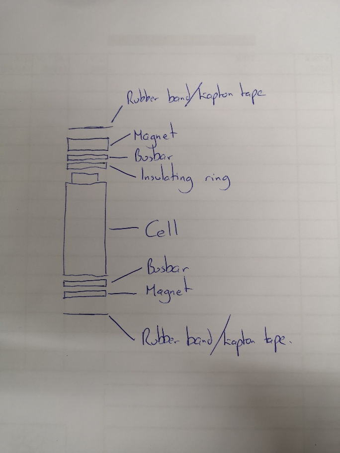
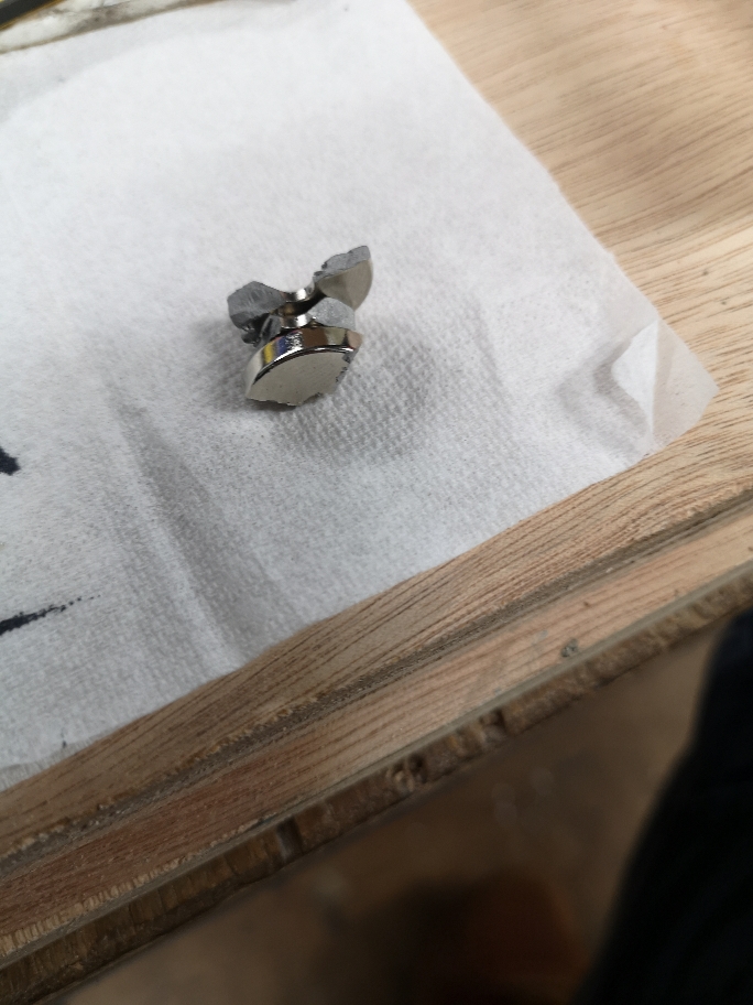
Although metal magnets conduct electricity, they have high resistance, so I would experiment with magnets over a copper strip. meaning that the copper strip is touching the cell-end. I think the copper should be thick enough to have a high current capability, but thin enough to still be flexible.
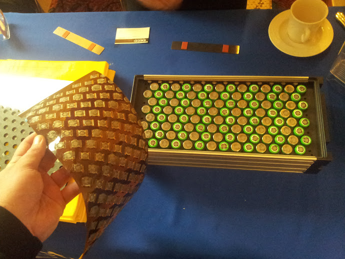
14S / 8P

20120328_132021.jpg


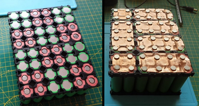
below, 12S / 4P (magnets held in place with super-glue, rubber-foam compression blanket, and hard side-plate)

BatteryMagnet3.png
 
Wow pretty inspiring, is there a build thread with details?

don't magnets wear out, lose power?

Did that design hold up to rough shock / vibrations?

And in the first one, is that all-one-big-sheet made of like plastic, with copper "floating islands" glued on the other side to give you the 14S8P?
 
I don't have any info on these builds. The top one was published and the builder was thinking about making the kits for sale, so he stopped posting the info. Its a flexible rubber sheet, electrically insulating, possibly silicone.

I don't recall info about the lower one either. I simply saw that it was interesting and saved the pic to show when the question comes up.

Unless the magnets get to 140F or higher, they should retain their holding power for longer than the cells retain their capacity.

The kind of magnets inside hubmotors are generally regarded as good up to 200F. If you price them out, they are surprisingly cheap
 
After a guick google... "Neodymium magnets are the strongest and most permanent magnets known to man. If they are not overheated or physically damaged, neodymium magnets will lose less than 1% of their strength over 10 years - not enough for you to notice unless you have very sensitive measuring equipment."

They do quickly lose their magnetism when exposed to temps over 80 Celsius though, which is well above what they should ever see under the circumstances. If things are hot enough in your pack to demagnetize them you're probably well past screwed already. :lol:
 
And are we sure there is no significant interaction between the strong magnetic field and the weak current flowing through it?

Any issue having one at each end?
 
Tesla have a patent that utilises magnets as part of their cell level fuse idea

https://patents.google.com/patent/EP2416405A1
 
edit: John, I don't know if a magnetic field interferes with current, thats a good question, needs an experiment. The previous battery pack builds like this seemed to work OK, so I'd be willing to risk the cost on my next pack build just to see. The magnets are cheap, and if it didn't work out, the undamaged cells could be re-purposed for a different method later.

A couple of builders tried magnets, and they worked fine, but interest died out. Pure nickel (and even nickel-plated steel) is perfect for the parallel connections. The current is less than 1/2 amp under all conditions, and the high resistance of the bus material slows equalization.

For the series buses, nickel is OK for low amps, but I like copper for higher amps. If a certain application is concerned about corrosion (near the ocean, with salty air), there are some suppliers now with nickel-plated copper, perfect for series buses, but...more expensive than simple copper sheet. Copper is 4 times more conductive than pure nickel, so a common 0.20mm nickel strip that is widely used for 10A peaks means that copper of the same size should be good for 40A peaks per cell.

The two thicknesses listed below will cut easily with scissors, and are still flexible.

0.20mm___8-mil__32 ga
0.25mm__10-mil__30 ga
https://www.riogrande.com/product/Copper-6-x-12-Sheet-32-Ga-Dead-Soft/132132

If you want to experiment, I would suggest soldering a fuse-wire to the positive end, which is quite robust and has several layers of isolation from the cells active material. The negative end is the part that is sensitive to heat, and that is where I would use a magnet to hold a copper ribbon onto it. There are cheap button magnets that have a hole in the center, and it is chamfered on one side so you can use a flush-head screw.

51ZfiDOhHUL._SX342_.jpg
 
So do you think something like this would be viable?

Excuse the fag packet sketch. You could do this to make individual parallel groups then connect in series using cable?

Or instead of rubber would heatshrink over the whole parallel group work?

If this looks viable I'll order a bunch of magnets and have a play. Won't cost me anything so worth a shot?
88164a6e601977d3de6f7cf2c955d98c.jpg


Sent from my CLT-L09 using Tapatalk


That looks good. The only connection of design concern is the series connections. The parallel connections are quite easy to make, and you can even solder a thin copper wire across the center of several copper ribbons to make the HHH shape.

As I said before, nickel is a great material for the parallel connections, but more expensive than copper wire, which can be salvaged for free. If you already have a roll of 8mm wide nickel ribbon, you can slice it with shears to 4mm wide and solder to the series ribbon.
 
Cool. For series these tabs have, well umm tabs with 5mm hole. So can attach these to decent size copper bus bar.

https://18650.lt/index.php/product/n-e-s-e-hardware-set-2/


Sent from my CLT-L09 using Tapatalk

 
I need some practice drawing in Pinta. This kind of drawing works very well in MS Paint, but I am no longer using Windows, and went to Linux.

CellCopperMagnet1.jpg

The parallel connection that connects one copper series strip to the other one can be a separate wire, copper or nickel, and it can be located anywhere along the strips. It can be a part of the copper sheet, such as cutting the copper into a U shape instead of H (seen below), with the parallel crossbar on the negative ends of the cells.

The electrons don't care where the paralleling "bridge" is during the cell-group balancing, as long as there is a path to get from one series strip to the next.

CellCopperMagnet1.jpg

Edit, here is one more option, The parallel strip can be on top of the magnets (shown here on the negative ends, none across the positives). I usually think of nickel as my default material for the parallel strips, but simple steel sheetmetal is cheap, locally available at hardware stores, and it will stick to the magnets (nickel is not magnetic)

CellSeries3.jpg

shopping for magnets: 5/8ths inch X 1/8 = 16mm x 3mm

Just bought 15mm x 4mm, N52 $0.70 each, (N35 strength is $0.40 each). Magnets arrived, very happy, they are very strong and will hold up a hammer on my tool-wall. The hole will pass #8 screws, but the flat-head protrudes hair. To have a truly flush flat-head, I am trying out #6 flat-head screws. Available in 1/2" or 3/4" length from the top of the flat head to the bottom tip.
 
spinningmagnets said:
edit: John, I don't know if a magnetic field interferes with current, thats a good question, needs an experiment. The previous battery pack builds like this seemed to work OK, so I'd be willing to risk the cost on my next pack build just to see. The magnets are cheap, and if it didn't work out, the undamaged cells could be re-purposed for a different method later.

A couple of builders tried magnets, and they worked fine, but interest died out. Pure nickel (and even nickel-plated steel) is perfect for the parallel connections. The current is less than 1/2 amp under all conditions, and the high resistance of the bus material slows equalization.

For the series buses, nickel is OK for low amps, but I like copper for higher amps. If a certain application is concerned about corrosion (near the ocean, with salty air), there are some suppliers now with nickel-plated copper, perfect for series buses, but...more expensive than simple copper sheet. Copper is 4 times more conductive than pure nickel, so a common 0.20mm nickel strip that is widely used for 10A peaks means that copper of the same size should be good for 40A peaks per cell.

The two thicknesses listed below will cut easily with scissors, and are still flexible.

0.20mm___8-mil__32 ga
0.25mm__10-mil__30 ga
https://www.riogrande.com/product/Copper-6-x-12-Sheet-32-Ga-Dead-Soft/132132

If you want to experiment, I would suggest soldering a fuse-wire to the positive end, which is quite robust and has several layers of isolation from the cells active material. The negative end is the part that is sensitive to heat, and that is where I would use a magnet to hold a copper ribbon onto it. There are cheap button magnets that have a hole in the center, and it is chamfered on one side so you can use a flush-head screw.

51ZfiDOhHUL._SX342_.jpg

the cheap button magnets with chamfered edge for a screw, why not just solder a copper wire or fuse wire into the hole instead of the screw, file the bottom flush and attach to battery and solder other end of wire to bus bar. that would be every cell fused with no solder and easily replaced
 
goatman said:
the cheap button magnets with chamfered edge for a screw, why not just solder a copper wire or fuse wire into the hole instead of the screw, file the bottom flush and attach to battery and solder other end of wire to bus bar. that would be every cell fused with no solder and easily replaced

I'm struggling to picture what you mean. Solder from busbar to where?

Sent from my CLT-L09 using Tapatalk

 
Just bought 2 packs of these. 6kg of force each so on 5p that'll be 30kg of pull on positive and equal on negative.
d99955868c01ad870fb287f56bd39971.jpg


Sent from my CLT-L09 using Tapatalk

 
Hickbeard said:
goatman said:
the cheap button magnets with chamfered edge for a screw, why not just solder a copper wire or fuse wire into the hole instead of the screw, file the bottom flush and attach to battery and solder other end of wire to bus bar. that would be every cell fused with no solder and easily replaced

I'm struggling to picture what you mean. Solder from busbar to where?

Sent from my CLT-L09 using Tapatalk

lNlq8Pl.jpg


RDOMuM9.jpg


maybe a dab of a dielectric grease?
 
Buy high quality magnets. The thicker magnets are stronger. 3mm or thicker. 10MM cubes will hang my hammers and all bike tools on an overhead steel pipe. There a fellow selling kits Battery Blocs. A waste of $$ and I've never bothered using them so they gather dust...

More expensive than China but you can see the ratings and holding power.

https://www.magnet4less.com/neodymium-disc-cylinder-rare-earth-magnets

N45 or N42

Their N52 are great! Mostly what I use.
NEODYMIUM MAGNETS N52 1/4 IN X 1/8 IN DISC
Strong N52, stronger than N50, N48, N45, N42 Pull force: over 4 lbs Magnetized through 1/8"
 

Attachments

  • Screen Shot 2020-01-27 at 4.47.29 PM.png
    Screen Shot 2020-01-27 at 4.47.29 PM.png
    68.8 KB · Views: 2,566
goatman said:
maybe a dab of a dielectric grease?
OLD school! Better to use ACF50 or Boeshield.
 
Hickbeard said:
Just bought 2 packs of these. 6kg of force each so on 5p that'll be 30kg of pull on positive and equal on negative.
d99955868c01ad870fb287f56bd39971.jpg


Sent from my CLT-L09 using Tapatalk

I was wondering if a person could glue a smaller diameter copper screw in the hole with plastidip or liquid tape or an epoxy, so it was insulated from the magnet for the positive side of the cell. the head of the screw is the contact point and you can bolt your copper strip to it or solder to it on the other end
the 18mm magnets ive seen have 5mm holes
 
@goatman oh I see what you mean now. So the bus runs alongside the cells instead of ontop.

Maybe a copper disc on top of cell with fuse wire coming off there to busbar.


Sent from my CLT-L09 using Tapatalk

 
Hickbeard said:
@goatman oh I see what you mean now. So the bus runs alongside the cells instead of ontop.

Maybe a copper disc on top of cell with fuse wire coming off there to busbar.


Sent from my CLT-L09 using Tapatalk

yes like a copper disc and wire but if its set in a flexible and insulated compound so the magnet cant short out the cell. if the disc is set in something like silicon 0.1mm below the surface of the magnet, the pull of the magnet could act like pressure from a spring. someone could make a decent dollar if they sold magnets with a pigtail wire like that.

4r7wChQ.jpg
 
What size fuse wire would I want?

The current dictates the wire size correct?

So does it want to be suitable for 1C or max current of cell 2.5C

Sent from my CLT-L09 using Tapatalk

 
Reading through this thread (not finished yet)

https://r.tapatalk.com/shareLink/topic?url=https%3A%2F%2Fendless-sphere%2Ecom%2Fforums%2Fviewtopic%2Ephp%3Ft%3D88039&share_tid=88039&share_fid=55725&share_type=t&link_source=app

If the max current of the system is 50a. I'd need to divide tht 50a by the number of cells.

So a 14s5p pack has 70 cells. 50/70=0.7a

So a 1a fuse would give a little headroom

The max current would be dictated by the controller right? So a 50a controller. Is tht 50a max or continuous?


Sent from my CLT-L09 using Tapatalk

 
Got some magnets in.

Soo... These little buggers are proper strong. But not strong enough to solely rely on.

And I've already broken one so 9 now which sucks for a 5p trial lol.

It's quite hard to keep them central though.

Could you solder a fuse onto a brass screw, screwed into a copper plate attached to the cell?
ee28f3580984d2c61a9ae06180e63425.jpg
af6059958b61c98fe8309f6339241b3e.jpg


Sent from my CLT-L09 using Tapatalk

 
Back
Top