Change the BMS for a bigger one?

MarkL

1 mW
Joined
May 3, 2020
Messages
13
Hi,

I bought a 3000W kit (72v 6500 RPM motor + 50A controller (with capacitors rated at 100V)) and a BMS 50A battery.

I am contemplating the idea of increasing the power output (amps, while keeping voltage at 72) of my battery to increase the rest of the chain already.

BUT, I want to make sure I get it properly first. The target voltage is 72V. Please correct my statements:

  1. The easiest way to do so is buying a new kit or at least matched parts.
  2. Upgrading the BMS from 50A to 200A will potentially decrease my Ah (autonomy) because I will be able to output more current to the controller, should it be rated high enough to feed a 8000w motor (generally 88-200A, taking peak amps into account).
  3. If my controller is rated at 50A, nothing will change, it will prevent any more current anyway. My 88A motor won't make its advertised power in all conditions (hills..) because I can only draw 50A anyway. It should approach its optimal perf on flat roads though.
  4. My driving style and hills may incur a dangerous heat increase for the battery.
  5. My battery may blow if the cells used are not up to the task (lack of cell quality)

May someone tell me if I got the gist of it correctly?

Thanks :wink:
 
1) The easiest way to do so is buying a new kit or at least matched parts.

Depends. If your controller is programmable and the FETs can handle higher current. If so, you could just reprogram it for more power. If it's not programmable, but have good FETs, you could gamble and do a shunt mod.
Safest option however is a controller designed for higher power.
2) Upgrading the BMS from 50A to 200A will potentially decrease my Ah (autonomy) because I will be able to output more current to the controller, should it be rated high enough to feed a 8000w motor (generally 88-200A, taking peak amps into account).

Upgrading the BMS does nothing in terms of battery capacity. The BMS current limit does not actually limit the current the controller can pull, it simply disconnects the battery from the controller if you overload it for an extended time. When pulling more current from the battery, the usable battery capacity does generally decrease, but this is not because of the BMS current rating.

3) If my controller is rated at 50A, nothing will change, it will prevent any more current anyway. My 88A motor won't make its advertised power in all conditions (hills..) because I can only draw 50A anyway. It should approach its optimal perf on flat roads though.

If your controller have a max battery draw current of 50A, changing the BMS does absolutely nothing. Do however note that battery and phase currents are two different things, and your motor might still receive 88A (or a lot more) even though the controller only pulls 50A from the battery.

4) My driving style and hills may incur a dangerous heat increase for the battery.

This depends on a lot of things. Battery cells, how the battery is designed and located, the outside temperature, how long the hills are, how steep they are, how heavy you are. In general with quality cells that are not being overloaded you shouldn't have any safety issues, but it's still recommended to have a BMS that disconnect if the battery gets too hot, especially if you intend to load the batteries higher then the pack was designed for.

5) My battery may blow if the cells used are not up to the task (lack of cell quality)

Not likely. They will sag like crazy and heat up a lot, but as long as you keep an eye on the temp you're usually not risking an explosion. If possible i'd try to find out what cells is used and stay below the max current draw. If it's a cheap Chinese no-name pack, expect it to already be overloaded at "rated" max current draw. Use a BMS with temp sensor for safety.
 
Thank you Jan-Erik,

I will buy the bigger motor and see what happens.
 
Hi,

I just opened my controller.
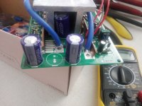
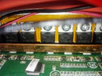
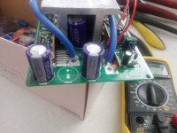
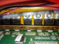
I have 100V 470µf capacitors and 24 HY3210 mosfets rated at 100V 120A.

Do someone has experience with those mosfets? My controller is a chinese no-name but I am surprised it has such stronger components for what I bought.

Thanks,

Edit: attached is the picture of it. In the middle of the 2 caps, next to the blue wire, are the 5 "bridges" my candidates for a shunt?

Edit2: Am I off topic on that forum with those precisions? Sorry if I am friends,
 

Attachments

  • IMG_20200504_153255.jpg
    IMG_20200504_153255.jpg
    114.9 KB · Views: 1,077
  • IMG_20200504_154527.jpg
    IMG_20200504_154527.jpg
    131.4 KB · Views: 1,076
Hi,

Can someone confirm this:
On the uploaded picture, is that where I can shunt my controller? Those 5 bridges next to the blue wire.
Most of the time, there is only 1 bridge.
Any word of caution? => should I add tin on all of them?

Thanks
 

Attachments

  • IMG_20200504_153255.jpg
    IMG_20200504_153255.jpg
    114.9 KB · Views: 1,076
HERE is the best shunt mod instruction thread and discussion short simple and to the point I have found yet.

https://endless-sphere.com/forums/viewtopic.php?t=31643

BTW... in the cornor of that board.. there is a number.. Kh.. or EB318, or 618...

What does your say? Out of curiosity? Its an 18 Fet board?

Yeah they did this stuff ten years ago.
 
Those 5 bridges are the current sensing shunts, yes. It's fairly easy to add some solder to them to increase the current draw, but it's very tricky to get exactly the current you want. I don't have experience with those FETs, but with a 24x 120A FET controller it's not likely to blow up from a light shunt mod by pulling a high power at short intervals. It will however likely heat up quite a bit more, so keep an eye on the temp.
It's never risk-free to do a shunt mod though, just keep it in mind and don't mod it if you can't risk it getting it ruined.. ;)
Also note that the power reading on the LCD will be incorrect, unless you use an external current shunt to measure power. You will need a current/watt meter to be able to do the shunt mod properly and know how much current it pulls.
 
Thanks,

in the corner it is written K S1.5.
Is it what you asked?

It is a 24Mosfet board made of HY3210
 

Attachments

  • IMG_20200504_154527.jpg
    IMG_20200504_154527.jpg
    131.4 KB · Views: 1,063
How do the shunts work and why does adding more solder help with more current? Could you measure the resistance and then add another piece of wire vs. adding solder?
 
Just a word of caution:

Remember that when you modify your shunts, the controller no longer has any idea how much current is actually flowing.

This means it can't protect itself against overcurrent, so you risk destroying it pretty instantly if current exceeds what it can actually handle.
 
@All,
I won't touch that controller, because I gathered a lot of info and the risk of collateral damage (when removing the fets) in non negligible.
All in all, buying a 200A controller (probably with more than 100V) is all I need and it is not that expensive in the grand scheme of things.

So I will go that route instead of creating a franken-controller. So many things can go wrong. So many things to modify..
 
Yes, but 250Nm of torque which should make up for it.. I weight 84kg, the prototype will weight 50kg.
Total: 134kg
 
I agree a new controller might be the best option if you can afford it, especially seeing that motor!

Did you find out what cells are being used in your battery pack though? Might be a good idea to make sure the battery pack can handle the extra power before buying a new controller.
 
Jan-Erik-86 said:
I agree a new controller might be the best option if you can afford it, especially seeing that motor!

Did you find out what cells are being used in your battery pack though? Might be a good idea to make sure the battery pack can handle the extra power before buying a new controller.

Yes there are two options: either buying a 144V 200A 18650 battery with a 200A BMS ($$$) or dying in the process of creating it, with the help/advices of an electrician.
 
I see. Do you have a link to the battery you are considering?

Although its not technically much harder to make a 100+v pack then a 12v pack, the risk involved is huge in comparison. While i would say go for it for a 24-52v pack, i wouldn't recommend that you put together a 100+v pack designed for 25+kw if you don't know what you are doing and have experience with electronics.

Around 60v is the limit for dry skin, but a 144v pack can actually be deadly if you are unlucky. The dc current from a battery also cause a completely different shock then the "vibrating" type you're probably familiar with when someone gets an electric shock from a wall socket. If you decide to build it yourself, use rubber gloves for safety.
 
I currently have no link for the battery since I decided to buy 38120s cells and do it myself ($).
I looked around and I will wear whatever gear will protect me.

Starting small (4S -> 12-14V and X amps) and as my knowledge increases, so will the volts and amps. 144V and 120A max output (and at least 21Ah) are the goal since my hub motor will support both.
Even if the controller doesn't need those amps from the battery to deliver them to the motor (phase current?), it will be simpler and less stressful on the battery to have it buffed up from the start.

I decided to add an anti-spark system as well:
http://askermodellklubb.no/wp-content/uploads/2012/02/antispark.pdf

Because I hate when it sparks.
 
Back
Top