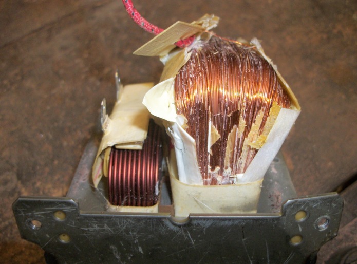
The input is typically 120V AC, and most home outlets have a 15A breaker, which limits common appliances (like a microwave oven) to 1600W. A transformer will "transform" the input watts to a magnetic field, and the steel lamination stack around the primary coil will pull-in and focus the magnetic field.
The only connection between the primary coil and the secondary coil is the pulsing AC magnetic field. And they both are located in the center of this field... This magnetic field induces an AC current in the secondary coil (with perhaps a 10% loss of watts due to energy conversion into waste-heat).
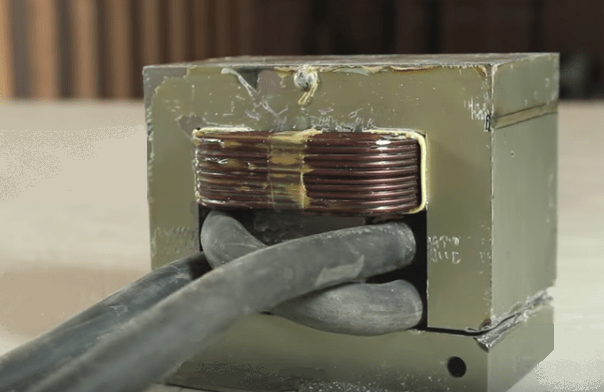
It is possible to weld certain things with the AC output, but a simple 4-diode "bridge rectifier" can convert the output into a DC pulse. So...now we come to the output coil. With all DIY transformer welders, the 2,000-strand secondary (using very thin wires) is removed and replaced with a low-turn-count coil using fat wires.
Since it is the heat of high amps that perform the welding, most builders focus on using fat output wires. There is a certain amount of space in the "window" of the transformer. Each turn is approximately one volt. The fattest welding cable is sometimes used to provide 2 turns, which is approximately 2-volts dividing the total watts of the magnetic field. Transformers come in many sizes, with 1500W being a common large size, and 1,000W being average (for a free trashed microwave).
Let's say the microwave is 1,000W input, with a possible output max of 900W if you squeeze-in the fattest possible wires. 12 turns would be 12V at 75A (= 900W). If you use 2 turns you can get as much as 450A, which would require a very fat cable to be squeezed into the window.
The max amps would be a rectangular cross-section of copper bar bent into a "U" so it would be a "one turn" output at 900A. So we can see how this explains the wire sizes. 1,000W transformer is 120V / 83A input, and the output would usually be 900W, 2V / 450A.