Hi All..
I am building a battery pack of my own design and received an unexpected result from the manufacturer. Mainly my bad for not considering the zero-point-something tolerance in the material. Now I have some doubt about the safety of the contact.
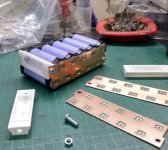
Parts & Assembly:
Its a nickel+copper bus kind of arrangement. Welded to cells using battery spot weld, to create a "module".
Each module then placed back to back to create series connection. Bolted at each end.

Nickel+copper bus looks almost exactly like this
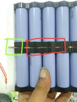
Worry Points:
1. The nickel tab of each module extend pass the copper. Obviously thats the most effective arrangement from the factory, but I failed to anticipate that during designing.
2. The extended nickels do touch each other (nice?), but it creates a slight gap between the copper (not sure).
3. At the end of the bus the bolt pinch the copper shut (nice), but it create a "gradient" in the connection (not sure)
4. With only 2 bolts (instead of 4) I can not guarantee an always proper contact in the middle of the "module" when the battery vibrate (road condition, shakes, etc.)

Questions :
1. Will the slight gap between the copper become a problem? (arching? hot? etc.).
2. Will the "gradient" contact near the bolt become a problem? (arching? hot? etc.)
3. Will a possible slight open and close (during vibration) in the middle of the "module" become a problem? Even if the bolt at each end maintain proper contact at all time?
Challenges:
- I've ordered plenty of these nickel-copper bus and can't afford to change the design.
- Expected peak Amp running between these connection is about 200A.
.
Any thoughts, comments, warning, and suggestions will be very appreciated.
I am building a battery pack of my own design and received an unexpected result from the manufacturer. Mainly my bad for not considering the zero-point-something tolerance in the material. Now I have some doubt about the safety of the contact.
Parts & Assembly:
Its a nickel+copper bus kind of arrangement. Welded to cells using battery spot weld, to create a "module".
Each module then placed back to back to create series connection. Bolted at each end.
Nickel+copper bus looks almost exactly like this
Worry Points:
1. The nickel tab of each module extend pass the copper. Obviously thats the most effective arrangement from the factory, but I failed to anticipate that during designing.
2. The extended nickels do touch each other (nice?), but it creates a slight gap between the copper (not sure).
3. At the end of the bus the bolt pinch the copper shut (nice), but it create a "gradient" in the connection (not sure)
4. With only 2 bolts (instead of 4) I can not guarantee an always proper contact in the middle of the "module" when the battery vibrate (road condition, shakes, etc.)
Questions :
1. Will the slight gap between the copper become a problem? (arching? hot? etc.).
2. Will the "gradient" contact near the bolt become a problem? (arching? hot? etc.)
3. Will a possible slight open and close (during vibration) in the middle of the "module" become a problem? Even if the bolt at each end maintain proper contact at all time?
Challenges:
- I've ordered plenty of these nickel-copper bus and can't afford to change the design.
- Expected peak Amp running between these connection is about 200A.
.
Any thoughts, comments, warning, and suggestions will be very appreciated.