10S balance plugs (2x5s) short protection?

pickworthi

100 W
Joined
Oct 1, 2020
Messages
129
Location
UK - Oxfordshire
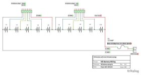
I've attached a diagram showing the wiring of a 10S battery I have built. The charging BMS will be me and a 4010DUO charger.
Discharge short protection is via 15 amp fuse - which is the maximum expected load through the e-bike motor controller (UK regs limited).

My question is about protecting the balance plugs against accidental short circuit. There is no mechanical protection available, since the plugs are identical. I have painted one black and one red, so I can tell which is which when the case is closed. However, there is always a risk that I'll plug them onto the balance board the wrong way round, at which point the red wire on plug 2 and the black wire on plug 1 create a dead short at battery voltage.

While this would probably melt the 22 AWG balance wires, that seems uncontrolled, and hence dangerous (possible runaway short if other balance cables melt and fuse together).

A solution I can think of is to place a fuse by the label "fuse here?" in the balance plug 2 red wire. A fast 2.5 amp fuse should allow the 4020DUO maximum balance current for example, and blow before the balance wires are damaged. Fuse would have to be rated for battery voltage.
I am assuming that the remaining balance connections in this scenario are OK, since there is no short circuit route between them.

Is this a sensible solution? I'm a bit concerned that the added resistance on that one balance wire might interfere with the balance process - but maybe the 4010DUO is smart enough to deal with that?

I'd really appreciate any feedback on this, thanks.
10S-balance-plug_schem-image.jpeg
 
Can you calibrate out the voltage drop off the fuse.
That's what you are doing when you ad a fuse

Gesendet von meinem CPH1911 mit Tapatalk

 
pickworthi said:
A solution I can think of is to place a fuse by the label "fuse here?" in the balance plug 2 red wire. A fast 2.5 amp fuse should allow the 4020DUO maximum balance current for example, and blow before the balance wires are damaged. Fuse would have to be rated for battery voltage.
A fuse is safe enough.

But you *can* actually key the connectors. You'd add some plastic to one of the connectors on either pack side or board side, and take out the same plastic off the one that mates with that. Then you couldn't possibly plug in the wrong one to the wrong port. At least, not without a bigger hammer. ;)


But first, is this "balance board" for the charger (or the charger itself) something that combines both of the connectors it has into a single parallel connection? I ask because this is the way most of them work, and it would be bad for your setup to do that. ;)

All the BBs I have here for the RC chargers I've got have multiple parallelled "input" connectors (from the packs), and a single (7-pin in my case) output cable and connector, that then goes to the RC charger's balance port. This is how most of the ones I've seen posted here work. But the cannot be used with seriesed packs...only electrically isolated ones.

The only kind that would work for your setup is one that has either two separate ports to the charger (which would also have to have two separate electrically independent ports, with NO internal interconnects between them), or a single port to the charger that contains all the necessary wires to keep both halves of your pack independent, so you don't short across any of the cells. (and two independent "input" connectors from the packs).
 
amberwolf said:
But first, is this "balance board" for the charger (or the charger itself) something that combines both of the connectors it has into a single parallel connection? I ask because this is the way most of them work, and it would be bad for your setup to do that. ;)

All the BBs I have here for the RC chargers I've got have multiple parallelled "input" connectors (from the packs), and a single (7-pin in my case) output cable and connector, that then goes to the RC charger's balance port. This is how most of the ones I've seen posted here work. But the cannot be used with seriesed packs...only electrically isolated ones.

The only kind that would work for your setup is one that has either two separate ports to the charger (which would also have to have two separate electrically independent ports, with NO internal interconnects between them), or a single port to the charger that contains all the necessary wires to keep both halves of your pack independent, so you don't short across any of the cells. (and two independent "input" connectors from the packs).

The balance board is this one:
https://www.nexusmodels.co.uk/balance-board-cb1010-xh-jst-for-icharger.html

I do not have a split pack. It is a 10S battery with two balance ports as shown. Thus, the battery negative goes to the charger negative, and the battery positive goes to the charger positive. The balance ports are plugged into the above balance board, presenting the two 5S connectors as a single 10S to the charger. That is the source of the potential short, on the board the two middle pins of the 5S ports are connected (since they are the same, i.e. zero potential difference, if the plugs are put in correctly).
I've just charged the pack, it works. This exact approach is described in the iCharger 4010DUO documentation.

amberwolf said:
But you *can* actually key the connectors. You'd add some plastic to one of the connectors on either pack side or board side, and take out the same plastic off the one that mates with that. Then you couldn't possibly plug in the wrong one to the wrong port.

I hadn't thought of that, nice idea, I'll see if I can arrange it.
 
monette999 said:
Can you calibrate out the voltage drop off the fuse.
That's what you are doing when you ad a fuse

Gesendet von meinem CPH1911 mit Tapatalk

The 4010DUO measures the individual resistance from each of the cells, it has a display showing all of them. It's documentation says it takes the cell resistance into account when discharging. It doesn't say it does the same when charging. I'm hoping it does, in which case it will "see" a cell with an apparent higher internal resistance, and compensate accordingly.

I'll guess I'll have to measure the end result of a balance charge and see how clever it is.
 
pickworthi said:
amberwolf said:
But you *can* actually key the connectors. You'd add some plastic to one of the connectors on either pack side or board side, and take out the same plastic off the one that mates with that. Then you couldn't possibly plug in the wrong one to the wrong port.

I hadn't thought of that, nice idea, I'll see if I can arrange it.
Another option is to use a board taht has 6s connectors, and use 6s connectors on your battery. Then cut one pin on each connector (different place on each one) and fill the corresponding hole in the mating connector, and you've also got a keyed connector. You'd have to ensure the wiring of each also matches, for connector and board--that means making your own board (perfboard and handwiring, or having a PCB made). So it's more work and more expensive, but it does work. ;)

There may also be keyed versions of the connectors you're using available somewhere. You only need one set taht's different frrom what you have already, to put on one connector set, and leave the other existing set, so since they're different they can't be plugge dinto each other. ;)
 
Many thanks for the suggestions. I hadn't thought of physical protection, so you opened up new possibilities for me here.

I think I may still follow up on your suggestion of making a custom balance board connector setup. It appeals to my engineer side.
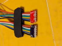
However, it occurred to me that I had a simple solution to hand, and it turns out to be serviceable. I took two strips of Polyethylene closed cell foam and glued them in a sandwich just behind the connectors. This holds the two connectors in the correct order. I would have to be really determined to plug them in incorrectly with this, during which time I would hope my brain would kick in before any connections are made :)

It's not pretty, but I think it will do as a solution for now.

Thanks again for the help.

PXL_20210125_143253931.jpg
 
Back
Top