Meanwell HLG-320H Series Combination Charging

vanturion

100 W
Joined
May 11, 2020
Messages
121
I searched and found some posts that mentioned the Constant Voltage HLG-320H series drivers could be combined in Series to boost the voltage output beyond the rated voltage output of each one. I couldn't find out much more than that so I ended up emailing Meanwell's technical support with a few questions.

My motivation was that I'm looking for a relatively cheap and reliable way to charge over 600W at 24S or 100.8V maximum. Considering that I already own both a HLG-320H-42A and a HLG-320H-54A, I was particularly interested to see if these two different models could be combined, the former at 45V (it's max voltage limit) and the latter making up the difference to get 100.8V output. I'll post up the responses I got verbatim as there may have been a bit of communication/effort barrier resulting in the responses I received.

1) "We are not recommend to use two different voltage for series, that might cause damage to the driver."

Then I asked for confirmation if it was OK if two -54As could be combined in series.

2) "Yes, you can do that."

Finally I asked about combining in series two -54s at different voltages such as 50+58V just as an example.

3) "You should keep the same output voltage when combing in series."

So, the confirmation was nice, but I'm still curious about whether or not using a -42A & -54A in series would, in actuality, result in damage as "might cause damage" was not a definitive answer IMO. It could be that the technician that answered me is just playing it safe and the risk is negligible, but I don't have the background to say one way or the other. I'm not willing to risk damage to these drivers as I use them both for different tasks, but I thought I'd pose the question to any electronic gurus before I go out and buy a second -54A unit.

Any guesses if this concern is valid and what electrical component(s) within the charger(s) are at risk for running both drivers at different voltages to combine their output in series?
 
Well I picked up a pallet load of HLG-240H-54A

intend one day to experiment doing just that, both parallel for higher power and series for voltage

cheap enough I could burn a few trying NP.

But they are in storage far away from me at the moment, hope to get back in the summer
 
dont mix different voltages. it kills them.

running identical models in series is no problem and i have been using that "trick" for nearly a decade for hundreds of installs.

without getting into the weeds of electronic enginerding you are "pushing" in more current into the higher voltage model then it can deal with. models like the HRPG actually have protections added to them so they fault out and shut down if they detect this. for this reason you MUST set both units up perfectly identical in voltage and current.

its not that it "might" cause damage, it will cause damage. especially when running them at max current and/or voltages.

its like you are using 2 engines to go forward but one engine is going so fast it starts pulling the other engine past redline. (massive simplification but it kinda visualizes what happens)
 
flippy said:
without getting into the weeds of electronic enginerding you are "pushing" in more current into the higher voltage model then it can deal with. models like the HRPG actually have protections added to them so they fault out and shut down if they detect this. for this reason you MUST set both units up perfectly identical in voltage and current.

its not that it "might" cause damage, it will cause damage. especially when running them at max current and/or voltages.

Ah, good to know. I still want to pick at this though because if the only problem is excess current going into the higher voltage model, the -54A in this case, then I should be able to limit the maximum current of the -42A to not exceed the -54A current limit by adjusting the built-in "Io" pot.

I have my 320H models hooked up to voltmeters that tracks current as well with an external shunt so it'd be pretty easy to start with small current and bring it up to match -54A lower current level at max output. Would this method be sufficient to prevent damage and account for Meanwell's technical assessment of "might" or is there more to it than that?
 
if 1 unit comes up faster in voltage the other unit will detect it and shut down. so beware it wont work every time you plug it in.
 
I'm also interested in this concept to charge a 20S pack (82-84V) - any recommendations? I'm also hunting around for a decent fixed-voltage charger but having the slight bit of adjustment typically found in a PS would be nice. (thanks)
 
Frank said:
I'm also interested in this concept to charge a 20S pack (82-84V) - any recommendations? I'm also hunting around for a decent fixed-voltage charger but having the slight bit of adjustment typically found in a PS would be nice. (thanks)

if you dont need waterproofing i recommend using the HRP series. a set of 2 HRP-300-36 would work and charge at 700~800W.
 
Would this method be sufficient to prevent damage and account for Meanwell's technical assessment of "might" or is there more to it than that?

Ended up posing this question back to the meanwell tech support and got back:

Yes, you can do that to make sure don’t excess the current rating for the lower one. Another thing, I would suggest you to add external blocking diode for each V+ and V- terminals to prevent the damage of the power supply while starting up. The voltage rating of the external diode should be larger than V1+V2 and the current rating should be greater than PSU rated output current.

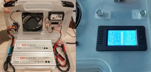
Nice! Result:
meanwell charger.jpg
The meanwell travel charger build handles 10S, 13S, and 14S independently as well as 24S in combination. Note: pic shows 6.3A exceeding the 5.95A current limit of the -54, I trimmed it back after taking the photo.
 
I’ll soon start a similar charger build. Did you end up putting the recommended diodes on it? What is the purpose, to stop voltage peaks at power up or shutdown events?

I thought that tvs diodes are placed in parallel with the circuit but then i wonder about the recommendation on current spec. The parallel diode isn't intended to shunt any charge current so why should it be rated for that?
 
Last edited:
Yeah, I suspected I was using them incorrectly and ended removing the diodes shortly afterwards. I'm not sure what they'd be protecting for when the load (battery) is consistent/known and the drivers can apparently handle series connections/higher voltage. Along those lines, it would be interesting to know what the actual maximum allowable voltage is for the drivers in series.

Anyway, about 30 kWh through the setup now and still working fine. That said, one slightly annoying quirk about this setup is that the current starts to drop off earlier than expected before nominal voltage, say 100.8V charging to 100% on a 24S battery, as the charging circuit (batteries) builds up resistance (reported on the charging display pictured above).

Example: let's say I want to charge at the maximum safe rate of 6A, so what I do is set the current to ~5.7A depending upon the beginning state of charge. Then, the current will climb incrementally during the initial phase of charging before leveling off and then decreasing again prior to reaching 100.8V, say 96V or so. If I catch it, I'll then ramp up the current pot again to ~6A.

Now I could just do nothing and it would still reach 100.8V before tapering current more dramatically like normal; however, there's this current pre-taper behavior that happens before the circuit sees 100.8V that tends to slow the charging process down a little. I don't know why this happens, but probably to do with running different model meanwells in series as this behavior doesn't happen when they're used individually. Just an FYI for anyone thinking about going this charging route.
 
How did you set the current the same on the drivers? What load did you use?

i thought about using a motor as load with about the same resistance as the battery pack but maybe this is overworking it, they should be regulating the current regardless of load (and come to think of it, the voltage driving the current is charger voltage - pack voltage so it’s regulated continuously)
 
I use two meanwell elg240 42V as on board slow charger in my scooter for charging the 21S battery. It is the version with current control through an external potentiometer.
Current setting is only done on one psu.
Setup is rumning since two years and has done over 1000hours of charging.
The chargers do a perfect cc/cv .
 
To asterisk what dominik said, since I'm running two different models -42A and -54A what I was describing above is not perfect cc/cv behavior, but close enough for my needs. Otherwise I would agree, identical models in series set at the same voltage would undoubtedly perform perfect cc/cv charging. My load is the 24S battery pack.

The pots in each of the drivers ("A" model) lets me trim both voltage and current. So basically to charge 24S I crank the -42A up to max voltage (45V) and the -54A to 55.8V to hit 100.8V. Then set the -54A current to max (5.95A). These 3 pots I don't touch again. The remaining -42A current pot I'll set at 5.5~5.7A (referencing shunt/display), making sure to stay under the 5.95A limit of the -54A.

Since there is some creep current creep both to the upside and the downside in the CC phase (abnormal), I'll trim up again if I catch it. I assume this has something to do with the way voltage and/or resistance is sensed in the circuit either running through two different models OR, more likely, because each driver is set at different voltage limits (45V and 55.8V). Maybe someone knowledgable about circuits can weigh in with the correct answer there.

without getting into the weeds of electronic enginerding you are "pushing" in more current into the higher voltage model then it can deal with. models like the HRPG actually have protections added to them so they fault out and shut down if they detect this. for this reason you MUST set both units up perfectly identical in voltage and current.

as flippy said earlier, there is a built-in protection feature I've tripped a few times trimming the -42A current limit too high above 6.3A which stops the charge until you trim it back again. So other than the minor amount of current creep in the CC-phase, no problems so far doing it this way for a couple years now.
 
Back
Top